Continue to Site

Welcome to our site!

Electro Tech is an online community (with over 170,000 members) who enjoy talking about and building electronic circuits, projects and gadgets. To participate you need to register. Registration is free. Click here to register now.

  • Welcome to our site! Electro Tech is an online community (with over 170,000 members) who enjoy talking about and building electronic circuits, projects and gadgets. To participate you need to register. Registration is free. Click here to register now.

Best input capacitor values to LM386 to cut all interference

Status
Not open for further replies.

mik3ca

Member
lm386+amplifier+with+gain+200.png


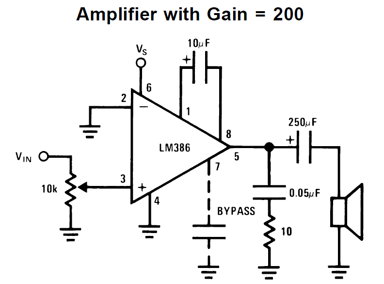
Yes, here's the classic LM386 again, but this time I want to filter things so I don't hear random internal noises. This circuit is connected to the same board as a few microcontrollers and an LCD (let's call it a working computer). And when each character on the display gets refreshed every 100uS, I hear through the speaker a low volume ticking sound which suggests local interference.

I still have a coupling capacitor from my sound chip on-board to VIN, but instead of 10uF, I made it 0.1uF. My setup is equivalent to the pot turned to max volume (10K to ground). Someone suggested I should add a capacitor across the same resistor

Question is what kind of frequencies should I really input-filter for and how do I select the proper capacitors?

I mean initially, I chose 10uF because I wanted all the signal to go through but when I ran the 10K and 10uF values through an online high-pass filter calculator, I get about 1.5 Hz

So I changed the 10uF to 0.1uF and after running sound tests on my system (when sound card is playing audio) before and after the capacitor change, the sound results are the same.

Then I go to the online calculator again changing 10uF to 0.1uF and I get 159 Hz filter.

Question is just how high of a minimum value can I set this filter to be? I mean what would be the lowest audio frequency the mass public would be able to hear anyway when it comes to normal audio and speech?

And do I put a capacitor across the 10K resistor to set it as a low-pass filter to under 20 Khz or can I even go lower and have people not notice audio degradation?
 
The datasheet of the LM386 shows that its input resistance is 50k ohms which is in parallel with your 10k volume control creating 8.33k that the input capacitor is feeding. Then a 10uF input capacitor produces a cutoff at 1.92Hz and a 0.1uF input capacitor produces a cutoff at 192Hz (no bass sounds). Normal audio goes down to 20Hz. A cheap clock radio produces no sounds below 150Hz. People can feel vibrations from a sub-woofer below 20Hz.

If you add a capacitor to ground at the amplifier input and it cuts high frequencies above about 3kHz then the audio will sound muffled like an old telephone or an AM radio, depending on the source resistance of the input signal. Normal audio goes up to 20kHz. Deaf old people without a hearing aid cannot hear high audio frequencies.

Your schematic does not show a bypass capacitor value at pin 7 but the datasheet shows that 50uF cuts power supply noises pretty well.

I don't know if the interference will be reduced enough if you cut important high and low audio frequencies.
 
Two things. First, a "tick" sound is a high frequency event. Adding a highpass filter (series capacitor with shunt amplifier internal input resistance to ground) will not affect the high harmonics like anything above 1 kHz. What you want is a lowpass filter. BUT, it will take a fairly complex filter to reduce the tick sound without rolling off all of the higher audio frequencies you presumably want to amplify. For a start, check out the "amplifier with bass boost" app circuit and frequency response plot. You might be able to combine this with the gain-of-200 circuit.

Second, try to determine how the tick is getting into the circuit. There is a strong possibility that it is getting in though the power or ground pins. To work on this, place a 0.1 uF (100 nF) ceramic, 1.0 uF film, and and 10 uF high quality electrolytic in parallel directly across the IC power and ground pins with the shortest possible lead lengths. If the tick sound is not reduced, this tells you to focus on the input. Leave the caps in place, because all audio power amp ICs require extra strong power supply decoupling.

ak
 
But not with an LM386
Actually ...

There is nothing explicit in the datasheet data nor the internal equivalent schematic that limits the LM386 low frequency capability to something above DC. The frequency response chart is flat to 100 Hz and the distortion chart goes down to 20 Hz. All of the low frequency gain characteristics come from external capacitors. Granted, most people don't put a $2 output cap and a $50 speaker on a 25-cent chip making only 1/2 W, but I don't see anything that says it won't work. For example, a 3900 uF output cap would lower the low frequency corner to 5 Hz into 8 ohms.

Note - you would need a second 3900 uF cap as part of the power supply decoupling.

ak
 
Last edited:
First you need speakers with a good Low Frequency Response.
 
The datasheet of the LM386 shows that its input resistance is 50k ohms which is in parallel with your 10k volume control creating 8.33k that the input capacitor is feeding.
Then a 10uF input capacitor produces a cutoff at 1.92Hz and a 0.1uF input capacitor produces a cutoff at 192Hz
Damn.... So I'll have to go with losing some low-end base sounds because if I buy capacitors higher than 0.1uF then they have to either by electrolytic or more expensive. Then again, I could put a couple 0.1uF in parallel but that would make my board more populated. But for now, I'll leave my cap at 0.1uF since the sounds are still acceptable. If I remember, electrolytics have a higher ESR and don't last as long as other capacitor types?

If you add a capacitor to ground at the amplifier input and it cuts high frequencies above about 3kHz then the audio will sound muffled like an old telephone or an AM radio,
....
Normal audio goes up to 20kHz.

So then I should make my capacitor value across the 10K such that it filters at 20Khz?


depending on the source resistance of the input signal.
The signal comes directly from the analog output pin of the ISD1760 chipcorder sound chip with no pull-up or pull-down resistor externally attached to it. How does the resistance affect the muffability of the sound (aka sound that gets muffled) ?

Your schematic does not show a bypass capacitor value at pin 7 but the datasheet shows that 50uF cuts power supply noises pretty well.
I take it the noise I have is still power supply noise even though the noise (the ticks) only happens when characters get updated on an LCD screen?

I don't know if the interference will be reduced enough if you cut important high and low audio frequencies.

Perhaps I should start with a range of frequencies to filter out. Question is what is the optimal range?

To work on this, place a 0.1 uF (100 nF) ceramic, 1.0 uF film, and and 10 uF high quality electrolytic in parallel directly across the IC power and ground pins with the shortest possible lead lengths.

For the parts themselves the lead lengths are short, but in my design I have multiple voltages. 7.2V from the battery connected to the LM386 via a long 10cm by 40mil track on PCB and the rest of the circuitry is powered with 5V via a LM2940 regulator with 22uF caps very close to it. I do have a 100uF capacitor connected directly to the 7.2V power line and ground as close to the amp pins as possible. I guess I should try the 100nF as well and see if it helps. maybe ESR of the electrolytic is the problem.

I may also look at scrapping the gain of the amp (disconnect everything from pins 1 and 8)
 
Ok I'm sort-of figuring out the root of the problem.

In my setup, I have a port pin of a microcontroller connected to a multivibrator trigger in a sub-circuit. Each circuit is connected together through a 3 foot serial cable. The value of this line changes about once every 1uS to send data to LCD in time to make the screen update.

Yes my circuit has a self-timer that triggers the LCD enable line when no new data comes in within a given amount of time. This saves me from requiring extra pins to the micro.

I measured the resistance of a wire in the cable and meter showed 12 ohms. I then tried to filter out high frequency by connecting this line to ground (at the subcircuit entry point with the LCD in it) via a 10nF capacitor and when I tried starting my system with that capacitor in place, it wouldn't run. As soon as I removed the capacitor, It runs fine but still produces that interference.

Because the micro is an 8051, the output going to this pin will always be ground or high-impedance.

What should I do here? should I add a pull-up resistor anyways or should I add a filter capacitor with a different value?
 
Actually ...

There is nothing explicit in the datasheet data nor the internal equivalent schematic that limits the LM386 low frequency capability to something above DC.

You're rather missing the point, I wasn't commenting on frequency response, but on the capabilities of an LM386 to produce enough power for people to 'feel' the sub-bass.
 
Damn.... So I'll have to go with losing some low-end base sounds because if I buy capacitors higher than 0.1uF then they have to either by electrolytic or more expensive. Then again, I could put a couple 0.1uF in parallel but that would make my board more populated. But for now, I'll leave my cap at 0.1uF since the sounds are still acceptable. If I remember, electrolytics have a higher ESR and don't last as long as other capacitor types?

ESR has nothing to do with audio, and the ESR of your non-electrolytics will be higher anyway - it's inversely related to capacitance, not capacitor type.

Electrolytics are perfectly fine for audio, and have been used for many decades in top quality audio equipment.
 
Last time I played around with an ISD chip it was the 2560. I had it connected to an amplifier (TDA7052) and I had a similar problem in that when sound files were 'fast forward skipped' on the ISD it would produce a low tick noise. It turns out the next file mechanism on the ISD 25xx is actually achieved by playing the file VERY quickly until it gets to the internal EOF marker. Basically the chip always made a slight noise when you skipped tracks.

Really annoying when you want track 10 and you get 9 fast clicks. In the end as it was all controlled by a micro and I had a spare pin I put a transistor from the ISD output pin and ground and altered the code to turn the transistor on during the skip routines and turn it off again for when it was playing. A sort of iternal mute if you will. That got rid of all the clicks.

I wonder if you have a similar problem with your setup rather than a filtering issue ?
 
Damn.... So I'll have to go with losing some low-end base sounds because if I buy capacitors higher than 0.1uF then they have to either by electrolytic or more expensive. Then again, I could put a couple 0.1uF in parallel but that would make my board more populated. But for now, I'll leave my cap at 0.1uF since the sounds are still acceptable.
I would use a small inexpensive 0.33uF (330nF) film capacitor to feed a 20k volume control at the 50k input of an LM386 power amplifier. Then its low frequency cutoff is very low at 33.9Hz.

If I remember, electrolytics have a higher ESR and don't last as long as other capacitor types?
An electrolytic capacitor might dry out in 20 years but you do not need one, a film capacitor is small, inexpensive and lasts for hundreds of years.

So then I should make my capacitor value across the 10K such that it filters at 20Khz?
The datasheet for the recorder IC says that its minimum AUX output load is 5k ohms so you cannot use a capacitor to ground. You also cannot add a capacitor to its speaker outputs.
Besides, you might need to filter out all sounds to cut the tick sound.

The signal comes directly from the analog output pin of the ISD1760 chipcorder sound chip with no pull-up or pull-down resistor externally attached to it. How does the resistance affect the muffability of the sound (aka sound that gets muffled) ?
AUX or SPKR output?
A lowpass filter has a series resistor that you do not have then a capacitor to ground. A capacitor to ground without the series resistor is a dead short at high frequencies.

I take it the noise I have is still power supply noise even though the noise (the ticks) only happens when characters get updated on an LCD screen?
Did you try powering the LM386 with a separate (6V to 9V) battery to see if the tick comes from the power supply?


Perhaps I should start with a range of frequencies to filter out. Question is what is the optimal range?
Filter out all audio frequencies. Problem solved.

I may also look at scrapping the gain of the amp (disconnect everything from pins 1 and 8)
Yes of course. The AUX output of the recorder chip is 1V p-p and the speaker output is a few volts p-p. Then the gain of the LM386 must not be 200. A gain of 20 with the volume control turned down is plenty. Then the tick might have a level that cannot be heard.
 
AG has just beaten me to it. A gain of 200 is a lot - are you really sure you need that much?
 
A capacitor to ground without the series resistor is a dead short at high frequencies.
Now maybe that's just what I need because the "tick" sound that happens at a high speed comes from the circuitry updating a screen on a sub-circuit. That sub-circuit is connected to the main circuit via a 3 foot cheap serial cable.

AUX or SPKR output?
AUX/AUD output.

Filter out all audio frequencies. Problem solved.
LOL if I did that then I'd hear nothing. but I want to hear speech out of a speaker, just not the annoying high-speed tick.

Yes of course. The AUX output of the recorder chip is 1V p-p and the speaker output is a few volts p-p. Then the gain of the LM386 must not be 200. A gain of 20 with the volume control turned down is plenty. Then the tick might have a level that cannot be heard.
Ok I'll see what happens when I do that.
 
I want to hear speech out of a speaker, just not the annoying high-speed tick.
If you filter away high frequency tick sounds then you will also filter away important consonant sounds of speech.
 
Status
Not open for further replies.

Latest threads

New Articles From Microcontroller Tips

Back
Top