TotalMadness
New Member
Hi,
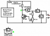
I found the attached circuit for building a simple bench power supply.
I am using all the components as in the schematic, but I cannot change the voltage down to zero. I have tested this with a LED (2.4v) as the supply output load and a mobile phone charger as the input source (5.3v 500mA). The description that came with the circuit is:
"The two transistors and three resistors form an adjustable, stabilised output. The FET transistor has a high output power handling capacity and a very low input power requirement and so is good for controlling the output voltage. Resistor ‘VR1’ is padded with the 4K7 resistor solely to reduce the voltage across the variable resistor. VR1 is adjusted to control the output voltage. If the current draw is increased and the output voltage is pulled down slightly, then the voltage on the base of the BC109 transistor is reduced. This starts to turn the transistor off, raising the voltage at point ‘A’, which in turn, raises the output voltage, opposing the variation caused by the load."
while testing, the readings I get are 3.1v and 8mA even when turning VR1. I checked VR1 and it does give readings of 0 to 5K ohms when turned. The voltages I get on the base of transistor BC109 range from 0 to 315mV. In fact, I can remove the BC109 transistor and I still get the same readings for the output.
I am using multimeters as shown in the schematic.
Any ideas?