Continue to Site

Welcome to our site!

Electro Tech is an online community (with over 170,000 members) who enjoy talking about and building electronic circuits, projects and gadgets. To participate you need to register. Registration is free. Click here to register now.

  • Welcome to our site! Electro Tech is an online community (with over 170,000 members) who enjoy talking about and building electronic circuits, projects and gadgets. To participate you need to register. Registration is free. Click here to register now.

bench grinder stopped working

Status
Not open for further replies.

1232sean

New Member
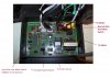
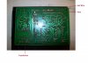
This morning I overloaded my bench grinder and it just stopped working. It is a variable speed benchtop grinder. I took it apart and discovered a circuit board, a lage capacitor, and a motor I am unfamiliar with. The circuit board had a small fuse that looked none the worse for wear. I checked it with my ohm meter and it appeared to give a reading on the 200 scale of 0.4 ohms. I don't know what it is supposed to read if the fuse is good. I thought that if it gave me a reading in ohms that it was intact. Next, I isolated the capacitor. It is a Dianz CB660 300V 18uF capacitor. I do not have a device that allows me to check capacitors so I went on to the motor. The motor has an unusual rotor. It is just a closed cylinder. I have no idea what is inside. The stator, on the other hand, looks like something I am familiar with. It has an iron core with copper coils. There are 4 wires that are part of the stator. There are 2 black wires that go to the circuit board and 2 white wires that form a closed loop with the capacitor. I checked the resistance between the two black wires and the resistance between the 2 white wires. I got a reading of 4.5 ohms and 11.5 ohms, respectively. I also checked the resistance between the black and white wires and got 4 different values for the 4 possible combinations. The first black wire and white wire A produced 4.5 ohms. The first black wire and white wire B produced 7.5 ohms. The second black wire and white wire A produced 0.4 ohms. And, the second black wire and white wire B produced 4.5 ohms. I dont really know what is going on here, so any help would be greatly appreciated.
thanks,
sean
 
I don't know what "you" mean by overload, however, three possible scenarios.

One: there is a thermal overload on the windings and it just opened, If you waited long enough it would reset.

Two: there is a thermal cutoff installed as has been toasted and will require a new one installed properly.

Third: You took out the variable speed control and if you do not know how to check a fuse then there is not much anybody can do to help you repair the variable control.

cheers
 
Last edited:
You did not say the fuse value but i suspect it's at least a few amps and less than 1 ohm on a meter would be fine, unless it's a fractional amp fuse and then it could be up to a few ohms.

What kind make and model meter do you have?
What is the fuse value?
How long did you wait before taking it apart?

cheers
 
My meter is a GB Instruments model # GDT-190A. The fuse says F6AL 250V. And, I waited about 30 minutes before taking it apart. The bench grinder is from a chinese manufacturer and is model # TLG-150VL. It says 2.5 Amps and 1/3 HP.
 
Last edited:
First - do you know for sure that the plug and/or circuit (and breaker/fuse in the box) are all "good" - that is, can you power a known-good load on that same outlet? I mean, its no good diagnosing a device if it isn't the device at fault...
 
Yes. My drill operates from the same outlet. And, I even used the same plug in this particular outlet and it is functioning correctly.
 
Last edited:
Yes. My drill operates from the same outlet. And, I even used the same plug in this particular outlet and it is functioning correctly.

Now - where the cord enters the tool, have you confirmed you still have power there (ie, it's not the tool's cord)? I know this seems elementary, but I'm just going step-by-step, because you didn't mention testing any of this. Next of course would be verifying the operation of the switch (such that you verify that power is available after the switch when it is on, and not when it is off)...
 
Sounds like a straightforward single phase induction motor to me. I'm guessing a basic phase angle Triac based circuit for the speed control. If the speed control is a simple phase angle "dimmer" type, the likely components to fail would be the trigger Diac or Triac itself. If the speed control is a little more elegant, then there's probably an Opto-Triac type device that triggers the Triac, and that would be the likely culprit along with the biasing resistors in the Triac gate circuit and snubber.
Of course as has been mentioned, it could simply be a fractured wire in the power cord, or a faulty switch etc.
 
OK. I checked the power cord and it registers about 123 V before it enters the switch. When the switch is in the off position, there are no volts from the output terminals of the switch. When the swicth is in the on position, the output terminals register 123 V. It appears both the power cord and switch are in good operating condition. Thank you, cr0sh, for being so methodical in your problem solving. I really appreciate a methodical approach.
 
OK. I checked the power cord and it registers about 123 V before it enters the switch. When the switch is in the off position, there are no volts from the output terminals of the switch. When the swicth is in the on position, the output terminals register 123 V. It appears both the power cord and switch are in good operating condition. Thank you, cr0sh, for being so methodical in your problem solving. I really appreciate a methodical approach.

Ok - at least the basic stuff is eliminated; that's good. I think now we'd want to start heading down tunedwolf's path. What would be useful here for us would be -clear- and detailed images of the circuit board, front and back (so we can see both components and PCB traces), with notes as to where power comes in (noting hot vs. neutral vs. ground) and power leaves (to the motor). If you are familiar with doing so, making a simple schematic of the components and how they are connected, based on the PCB and traces, can be helpful. Otherwise, someone here can probably do so based on the images you provide. Note that the best way of creating these images is with a scanner, but if that isn't possible, use a digital camera (hopefully one with auto-focus), proper lighting, etc - so-as to create the best quality images as possible.

Once we know the layout of the circuit, we can suggest ways to probe it to verify that the electricity is flowing in and out of it correctly (or not, as the case may be). Hopefully, it's a part on the PCB that's failed, and not the stator windings of the motor.
 
Ok. I circumvented the circuitboard by plugging the leads to and from the motor onto the output terminals on the main switch. I plugged the power in and turned the switch on and the grinder started working. At least we know it is not the motor that is the problem. If it is the switch that might be the problem, is there a way to just check to see if it is functioning properly instead of having to go into checking everything on the PCB. I believe the variable speed switch is a dimmer type switch like tunedwolf thought. The single line that leads to and from the switch has three wires in it. It plugs into the PCB. The other component that I believe is part of this variable speed function is a sensor mounted just outside the motor housing. There is a gear-type wheel that is fixed to the shaft of the motor whose cogs rotate through this sensor. There is a single line that leads to and from this sensor. It also has three wires in it. This line also plugs into the PCB in a similar fashion as the variable control switch. It actually plugs in right next to where the variable control switch plugs in. If it is necessary, I will take pictures of the PCB on both sides and upload them. Thanks for all your help.
sean
 
If the shaft has a sensor on it, then the speed control is much more elegant than I originally thought, likely using a tacho of some kind for feedback. I will need some decent quality photos of the whole rig, both sides of the pcb, wiring, sensor etc to proceed with anything sensible. I can really only make assumtions from this point without something more to go on...

rgds
 
pictures

Lets try it again.
 

Attachments

  • 101_0757.JPG
    101_0757.JPG
    2.6 MB · Views: 780
  • 101_0758.JPG
    101_0758.JPG
    2 MB · Views: 834
  • 101_0759.JPG
    101_0759.JPG
    2 MB · Views: 791
Ok, it looks like a variation of a washing machine speed control, most probably using a TDA1085C (16 pin chip) or one of the chips in that range. Things to check are the voltage across the 100uF capacitor sitting vertical right in the middle of the board in front of the Tacho connector. You should have somewhere around 14-16 Volts across it, if not, suspects would be the transformer, or the two square yellow capacitors at the corner of the board, or the diode in the middle of the two resistors where it says D21 or one or more of the diodes beside the yellow capacitors etc.

If the 15V is missing, lift one end of the diode above where it says D21 and try soldering a couple of wires to the pcb at the 100uF capacitor and inject a maximum of 15V, watch your polarity and voltage as a mistake here will blow the control chip, also remember to use an isolated supply, as one side of this supply will be at mains potential when connected. If the speed control runs ok, the problem lies with the power supply built around the transformer/ yellow capacitors. diodes and the scr's etc, if the speed control doesn't run with an external supply, then check the opto couplers and the 820K resistors, one of which is above the triac on the heatsink and the other in front of the optocouplers.

Obviously quickly check all the other diodes, but I think they are unlikely to be faulty.
It could be one of the small capacitors around pins 4-7 but again, without testing them there's no way to be sure.

rgds
 
Last edited:
The other day when I started checking the capacitor for voltage across it, I got a reading of 11.85 V. Unfortunately, I also broke the leads wire that comes off the dimmer switch. I have decided that the variable speed capability is not absolutely necessary. Therefore, I am not going to bother replacing the dimmer switch and then troubleshoot all of the possible things that could be wrong with the circuit. What I would like to do, however, is put a fuse in line with the power in order to keep from burning up the motor. The motor is rated for 2.5 amps. My question is: What rating fuse do I need, and Where do I put it exactly?
thanks,
sean
 
Ok, we can just remove the speed control entirely. If you want to protect the motor itself, the fuse rating pretty much depends on the starting current for the motor, this will always be a little higher than the flc (full load current) on the rating plate. Motor rated fuses should be used (HRC Ceramic/ Sand filled) or a motor rated breaker. Equipment fuses normally only protect the power cord and mains wiring in the event of an overload, not the actual equipment.
For such a small motor, I would think 3.15A will happily take care of the starting current and still be well within the rating of the power cord.
The fuse should be fitted in-line with the hot lead (live) as it enters the equipment, prior to any on/ off switch.
Obviously the Neutral lead goes straight to the on/ off switch if a double pole type switch is used, and straight to the load if only a single pole type is used.
The Ground or Earth connection stays where it is.

rgds

I forgot to mention that if you use a chassis type fuse holder, the hot lead goes to the contact that you cannot touch when the fuse holder is open, i.e the bottom connection.
 
Last edited:
Status
Not open for further replies.

Latest threads

New Articles From Microcontroller Tips

Back
Top