Continue to Site

Welcome to our site!

Electro Tech is an online community (with over 170,000 members) who enjoy talking about and building electronic circuits, projects and gadgets. To participate you need to register. Registration is free. Click here to register now.

  • Welcome to our site! Electro Tech is an online community (with over 170,000 members) who enjoy talking about and building electronic circuits, projects and gadgets. To participate you need to register. Registration is free. Click here to register now.

Behringer MX 1602 mixer - reading block diagram

GuitarMan

New Member
I have the abovementioned mixer. As is often the case, it is advertised as having more channels than it actually does, because, for instance, there are 4 channels with stereo inputs, which they count as 2 channels each, but are mixed at the input and treated as a single channel with only one set of controls. Looking at the control surface, you can see 8 channels, and that is what you get.

There are other shenanigans, too, like only one side of a headphone set working, or only one of the LED meter ladder pair tracking the mains, which makes no sense.

The manual, which is attached here, has large gaps in the information it provides, but it does contain both a schematic and a block diagram.

My ability to relate the physical controls to the schematic is limited. I do better with the block diagram. My problem is that even in the diagram, there appear to be points which are best described as "... and then magic happens ..." which is not good.

I am trying to figure out why the pair of LED meters do not track the main left and right outputs, as they would in every mixer I have ever encountered. From the block diagram, it appears that they should.

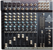
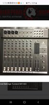
I am attaching images of the mixer as well, so you can see the physical controls (which is what I need to work with).

All of the controls, including the LED ladders, work if you set them in particular ways, so it's not a failed part, or at least it doesn't look that way.

Here is where I lose my way in the block diagram:

Looking at the "CTRL ROOM AND PHONES" section (lower right),

The switch at the upper left corner of that section is labeled "2TK to CTRL R". It selects either the main post fader outputs or the "2TK/stereo aux ret 2" (lower left of block diagram).
Where is the corresponding physical switch in the controls ?

From there, the signal travels to a DPST switch, which selects either the main post fader outputs or the "PFL/Solo" signal.
Where is this corresponding physical switch ?

Another switch above the DPST connects the right meter.
Where is this switch ?
 

Attachments

  • Behrenger MX1602 Mixer SCH(schem only 8pg).pdf
    473.4 KB · Views: 24
  • behringer-mx-1602a-user-manual(manual+block).pdf
    340.7 KB · Views: 17
  • mx1602 block.png
    mx1602 block.png
    111.5 KB · Views: 33
I have the abovementioned mixer. As is often the case, it is advertised as having more channels than it actually does, because, for instance, there are 4 channels with stereo inputs, which they count as 2 channels each, but are mixed at the input and treated as a single channel with only one set of controls. Looking at the control surface, you can see 8 channels, and that is what you get.

That's perfectly normal among mixers, they count the inputs, not the channels.

There are other shenanigans, too, like only one side of a headphone set working, or only one of the LED meter ladder pair tracking the mains, which makes no sense.

Which meter doesn't work?, is it the right one? - the block diagram, and schematic, clearly show a muting option on the right meter - with the left one always connected.

Presumably, it's for when you have Solo pressed, and it's only showing one input, so only needs a single mono meter.
 
he switch at the upper left corner of that section is labeled "2TK to CTRL R". It selects either the main post fader outputs or the "2TK/stereo aux ret 2" (lower left of block diagram).
Where is the corresponding physical switch in the controls ?

From there, the signal travels to a DPST switch, which selects either the main post fader outputs or the "PFL/Solo" signal.
Where is this corresponding physical switch ?

Another switch above the DPST connects the right meter.
Where is this switch ?
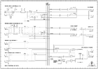
From a quick look;
2TK to CTRL R is the at the very bottom right, above the control room / phones output level pot. SW 22 A & B

(Control room - phones - monitor are all apparently the same output pair).

"DPST switch, which selects either the main post fader outputs or the "PFL/Solo" signal"
Button above the master output faders?

"Another switch above the DPST connects the right meter."
Same one, SW 20; it's a multi-pole switch - 20 B, the two above are 20 C and 20 D
 
Thanks to everyone for their replies.

Ron Simpson, it's been here a long time (like me). I think somebody needed room in their closet and put it in mine.

Yeah, I thought it would show main left and right, too, but that ain't happenin'.

Nigel, yeah, I know, it just bugs me that they call an input a "channel". Truth in advertising. I have a Tascam 388, which has inputs all over the place, and they STILL call it an 8 channel mixer.

Both meters work, which I know because when you put a channel into PFL mode and then press the PFL/Solo button in the main section, they both light up, all the way if the signal is high enough.

What does NOT happen is that without PFL engaged at channel and main levels, all I get is the right meter.

From the block diagram, it looks to me like it's the LEFT meter with muting - it has a switch that can go to ground, but with PFL off it STILL doesn't light up that left meter. The right one works fine in non-PFL/Solo mode.

RJenkinsGB, I stared at the block diagram after a few hours of sleep, and this what I see:

The "2TK TO MIX" button sends the "2TK/AUX RET 2" signal.
When open: nowhere.
When closed: to the main L/R buses.
This button switch is in the main control area, immediately below the "AUX RET 1" gain pot.

The "2TK TO CTRL R" button selects:
When open: the main post-fader outputs and send them toward the 3PDT switch.
When closed: the "2TK/AUX RET 2" signal and sends that toward the 3PDT switch.

The 3PDT switch selects:
When open: sends output of "2TK TO CTRL R" switch to both meters.
When closed: sends PFL/Solo signal to L meter, "CTRL R" and PHONES.

So with "2TK TO MIX" button up/open,
and "2TK TO CTRL R" button up/open,
and the 3PDT switch up/open,
the main L/R should hit both meters.

The button above the master faders is labeled "CHANNEL MODE", with "PFL(up)" and "Solo(down)" written above the button. That lets you choose either the PFL or Solo signals, and is not the 3PDT switch we are looking for.

So that mystery switch is the one I need to identify.
 
Here's a picture of the mixer I used at our gig the other week, it's a Studiomaster which we bought cheap as it was faulty, and had no PSU - I repaired it, and made a PSU for it (17V+/17V-).

Notice the 9th blue button from the left is depressed (more obvious from this picture that it was at the time), it's a solo button on a channel I wasn't even using :D

HULD6392[1].JPG
 
The button above the master faders is labeled "CHANNEL MODE", with "PFL(up)" and "Solo(down)" written above the button. That lets you choose either the PFL or Solo signals, and is not the 3PDT switch we are looking for.

All the signal routing to the meters beyond the "2 TK TO MONITOR" switch is done by FETs acting as analog switches, controlled by logic signals.

SW20, PFL/Solo is used to select audio signals it the lower left of sheet 6, and another gang of SW20 is used at the right of that sheet to disable the right level meter, via a FET switch..

The logic signal that controls selection between normal stereo outputs and the PFL/Solo source is "SOLO_FET" which appears just right of centre in in that sheet.

I cannot so far find where that comes from. SW20 is actually a four pole, as 20B, 20C and 20D are on sheet six; 20A presumably exists somewhere?


Logically, if all the SOLO switches on the channel sections are off, and PFL is off, that should allow the main mix to the meters? Any channel SOLO switch on will cause re-routing.


Edit - found the FET switch control; if any of the channel SOLO switches are on, they ground a signal called ENABLE, which passed through an opamp comparator on sheet 7, and the output of that changes the meter mode and enables the LEDs connected to SW20A, which indicate PFL or SOLO.

If either LED is on, SOLO has been selected on a channel, which results in the meter mode change as I thought.
 
Last edited:
it is advertised as having more channels than it actually does
Years ago, I switched from R-R tape recorders that were too heavy to lift, to digital recorders.
1748026864086.png

I know what a 2 channel and a 4 channel tape deck is.
My first two digital recorders clearly are labeled 8 channel. They can play back 8 channels but can only record 1 or 2 channels at a time. It can hold 50 tracks of the same song. You can edit 8 tracks at a time. We did some very complex recordings on them but not what I thought.

Next digital recorder could record 16 tracks at a time while playing back that many. (not a 32 track machine) IMO
------------------------------------------------------
When I look at a mixer I count how many mick channels, how may faders. I do some complex things so I need to know how many busses there are. It is easy to not understand that the numbers mean.
--------------------------------------------------------
I am trying to figure out why the pair of LED meters do not track the main left and right outputs, as they would in every mixer I have ever encountered. From the block diagram, it appears that they should.
In the broadcast world the heat phones and meters do many jobs.
Most of the time you are monitoring the main output.
In SOLO mode you are not on the main outputs. Often only one meter works and only one headphone channel works to tell you this is SOLO mode. Think about years ago when announcers had to find the right place on vinal or tape. In SOLO mode you can listen to one input and get the next song lined up. On today's mixers I often use Aux1 for this purpose.
 

Latest threads

New Articles From Microcontroller Tips

Back
Top