Continue to Site

Welcome to our site!

Electro Tech is an online community (with over 170,000 members) who enjoy talking about and building electronic circuits, projects and gadgets. To participate you need to register. Registration is free. Click here to register now.

  • Welcome to our site! Electro Tech is an online community (with over 170,000 members) who enjoy talking about and building electronic circuits, projects and gadgets. To participate you need to register. Registration is free. Click here to register now.

beginner: voltage-divider biasing of transistors

Status
Not open for further replies.

nyoo

Member
Hi,

Please could someone clear up a doubt about transistor biasing?


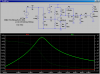
The "receiver" in the attachment is listening for a 1kHz square wave at 87.5 MHz FM. From the US FCC regulations, the incoming signal strength should be about 0.2 mV and 50 uA.

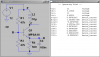
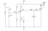
The MPSA18 amplifier has Vbe(on) = 0.7 VDC and hFE = 400. I used one of the on-line "voltage divider biasing" calculators, to convert the MPSA18 characteristics into the 39K/27K/3R3/560R values.

Here's what I can't see. The R1/R2 voltage divider give 4.6 VDC. If so, is a biased transistor's voltage always on? And if so, is the meagre 0.2 mV from the antenna irrelevant?

If a transistor is a current-controlled device, is the current through the potential divider more than enough to keep the MPSA18 permanently on? Should I calculate that as:
12 V / (39+27) KOhm = 180 uA?
And if so, will the 50 uA from the antenna make any difference?


How does this work? I'm missing something very basic and obvious.

Thanks a lot.
 

Attachments

  • MPSA18.JPG
    MPSA18.JPG
    22 KB · Views: 905
Last edited:
The transistor will be turned on all the time, but as long as it never saturates, that is OK because variation in base current will cause variation in the collector current.

The 0.1 uF capacitor to ground makes the AC gain much bigger that the DC gain, but it is still tiny because the 3R3 is far too small. You should have more like 680R. Then the output swing would be a lot larger. If the input current is actually 50 uA the transistor will saturate some of the time because the output will be so big, but with say a 10 uA swing, the output voltage will vary by about 10 uA * 400 * 680 R = 2.7 V, which should turn on the next transistor.

You also need a diode from ground to the connection between the 0.1 uF and the diode that you already have. 1N4148 diodes have a lot less capacitance and will work much better.
 
Last edited:
Diver300, thank you. You have solved my problem. I will swap out the 3R3, add the diode, and make all the diodes 1N4148s.

You solved my problem, but I still don't know how the magic was done.

I have this 180 uA travelling down from my power source through the the 39K resistor, and 50 uA ( or sometimes nothing) coming from the antenna. Your answer leads me to conclude I just ignore any current associated with the 39K/27K potential divider. And the Vout is controlled by the (now) 680R. So what's the left-hand divider for?

The new diode you recommended, please could you explain what it does, and which end gets the cathode?

Thanks.
 
Last edited:
For a transistor to amplify, it must not be turned completely off or completely on. The 39k/27k potential divider makes sure that the transistor is partially turned on.

If the voltage at the base of transistor changes, the voltage of the emitter will change by about the same amount. The change of current in the emitter depends on the impedance of the emitter resistor. At high frequencies the capacitor on the emitter makes the impedance of the emitter very small, so there is a large current change in the emitter current and therefore in the collector current. The change in collector current gives a large change in output voltage.

The extra diode's cathode connects to the anode of the diode that is in your circuit diagram. The anode of the extra diode connects to ground. The diode is there because you can't get current through a capacitor for longer than a very short time. When the collector of the transistor goes positive, current will go through diode and charge up the 470 uF capacitor. When the collector goes negative, there needs to be a path to put current into the right side of the 0.1 uF, and that is what the extra diode is for.
 
Thank you very much.

Transistor biasing is much clearer for me now.

As a bonus, you validated and corrected a beginner's home-brew circuit!
 
I came up with several improvements based on LTSpice simulation:

First, note that the resonant freq of the tank is ~58MHz, lower if you considered stray capacitances.
Second, by optimizing the bias and replacing the transistor load with a 10uH RF choke, I got about 10db more gain out of it. Note that the collector is now at 12V (Choke has ~zero dc resistance), and I upped the quiescent collector current. The transistor now has ~20db gain at the resonant freq when the input is +_70mV. See the ac sim, which shows the gain from the input IN to the collector C.

I used 1n34 Germanium diodes instead of Si diodes, with a bit of bias. This greatly raised the detection sensitivity. I optimized the coupling caps for appropriate time constants. The 470uF was too huge by several orders of magnitude. The time-domain sim shows the response at the RELAY to a 70mV, 58MHz burst, which is about the lowest amplitude that can be reliably detected.
 

Attachments

  • DF68f.png
    DF68f.png
    46.1 KB · Views: 268
  • DF68t.png
    DF68t.png
    29 KB · Views: 261
Last edited:
MikeMl, thanks for your calculations. I'll include the changes.

But oh dear!

If the resonant frequency of the tank is 58 MHz, then the circuit is not tuned to listen for 87.5 MHz, correct? Am I using the wrong formula(e)?
C = 1/(1/33 + 1/27.6) = 15.03 pF
f = 1000/(2*pi*sqrt(.22 uH * 15.03 pF)) = 87.5 MHz

The (former) 470 uF capacitor and the resistor at the base of the 2N3904 were supposed to provide a time delay before switching off that transistor, after the antenna signal stopped. How would I achieve that?

Thanks very much for your help.
 
Last edited:
In the simulation, the tank circuit is loaded by the extra 3pF I used to couple the signal in, and the input capacitance of the transistor, both of which add up to lower the resonant freq.

The problem with the 470uF is that it delays both the initial detection, and the decay after the signal goes away. You need some sort of fast attack, slow decay circuit. I would put a resistor pull-up in place of the relay, and then add the delay circuit downstream of that. A 555 would work nicely, and it can drive the relay if you really need a relay.
 
Whew, that's a relief! So with a 4-40 pF variable capacitor, your 3 pF capacitor can stay, and the tank will still tune to 87.5 MHz?

Yes, the relay is required. It switches on a 20 A 115 VAC fan. The circuit actually would benefit from a few seconds' delay starting the relay, and stopping it. It was an attempt at hysteresis. Please may I have an electrolytic capacitor there, somewhere between your 10 nF and the original 470 uF?
 
The diode detector will act like a current source (250uA at 70mV input). With a 470uF capacator, it will take several seconds for the relay to pick up, and then it will hold the relay on for about the same time.
 
Two questions remain for me. If I could please borrow another cubit of your time.

1. Why doesn't any of the current flowing down the (now) 47K / 47K voltage divider flow to the base of the MPSA18? Why doesn't that current swamp the meagre 50 uA from the tank?

2. After the introduction of the 3 pF, the tank oscillator frequency went from (calculated) 87.5 MHz to (simulated) 58 MHz. Is there a way without Spice to rough-caclulate the value of the variable capacitor needed to let the tank pass 87.5 MHz now?

I'll read up on the "input capacitance of a resistor". I've not encountered that before.

Thanks again.
 
Last edited:
1. Why doesn't any of the current flowing down the (now) 47K / 47K voltage divider flow to the base of the MPSA18? Why doesn't that current swamp the meagre 50 uA from the tank?
Some current from the top 47k resistor flows into the bottom 47k resistor to produce the DC bias voltage and a very small current flows into the base of the transistor. It is the DC bias voltage and current that turns on the transistor a little so it is ready to amplify the AC signal from the tuned LC tank circuit.
The signal from the tank is a voltage signal that modulates the DC bias of the transistor so it amplifies the signal.

2. After the introduction of the 3 pF, the tank oscillator frequency went from (calculated) 87.5 MHz to (simulated) 58 MHz. Is there a way without Spice to rough-caclulate the value of the variable capacitor needed to let the tank pass 87.5 MHz now?
You also must guess about how much is the stray capacitance. So calculations are almost useless. Simply build the circuit and adjust the trimmer capacitor or the number of turns and their spacing of the coil.

I'll read up on the "input capacitance of a resistor". I've not encountered that before.
It is not the resistor that has capacitance. It is the type of wiring connected to the resistor. If the circuit is built on a breadboard then the capacitance between wires and between tracks is very high and your 87.5MHz circuit probably will not work.
 
1. I'm going to use the power of LTSpice to answer that. I isolated only the bias part of the circuit, and asked it to show all of the DC voltages and Currents (with no input signal). Note I(R1), I(R2), and Ib(Q1).

2. It is not the input capacitance of the resistors that matter, even though at ~100MHz they do exhibit some between their two ends. It is primarily the base to emitter and base to collector internal capacitance that shifts the resonant frequency. My little 3pF accounts for about half of the delta from 87 to 58 MHz. The rest is due to the transistor. When you build the circuit, the shift will be even worse, due to the stray capacitances of the wires, pcb traces, the bias resistors, the capacitor bodies, the coil turn-to-turn capacitance, etc. Hint, when you build it, you will need to reduce C1.
 

Attachments

  • DF68b.png
    DF68b.png
    25.8 KB · Views: 221
Gentlemen, thank you all. I do appreciate your sharing your experience.

I see the very low Ib(Q1). And you've left enough hints to prove how it got so low.

Thanks too for saving me from using a verboard. This will be my first "squashed fly" soldering arrangement, for the amplfier and tank anyhow. I'll keep the resistor leads short. And C1 will have some lower value understudies.

Who knows, maybe it's even time to try LTSpice again?

Thanks again.
 
Last edited:
I used Veroboard (it has parallel copper strips, it is not a breadboard) to build my FM transmitter that works perfectly. I cut all the traces to length with a drill bit and tightly packed the parts so that stray capacitance is minimal.
 
Yes, I'd forgotten about the oft-discussed audioguru FM transmitter until after I posted! I'll use your shortened-tracks technique. Thanks.
 
One guy built an FM transmitter that didn't work. He used perforated board about the size of my bedroom with the parts far apart and had long wires all over the place.
 
Status
Not open for further replies.

Latest threads

Back
Top