Continue to Site

Welcome to our site!

Electro Tech is an online community (with over 170,000 members) who enjoy talking about and building electronic circuits, projects and gadgets. To participate you need to register. Registration is free. Click here to register now.

  • Welcome to our site! Electro Tech is an online community (with over 170,000 members) who enjoy talking about and building electronic circuits, projects and gadgets. To participate you need to register. Registration is free. Click here to register now.

beginner: simple audio amplifier

Status
Not open for further replies.

nyoo

Member
Hi.

Please could someone advise on a small circuit that takes an electet microphone as input, output going to a set of 8-ohm headphones? I searched current threads on the forum and heard discussion of "emitter resistors, feedback decoupling capacitor, input coupling capacitor, class AB". I'm a bit lost.

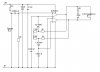
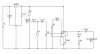
Mostly I'm trying to follow the Application voltage gain reduction (BTL) circuit described in the datasheet for the NJM2073. In terms of output sound, I was trying to get a high-pass filter with cut-off frequency near 2000 Hertz, and a 30-40 dB gain thereafter.

So, a bunch of small questions.

1. Does the electret 2-wire microphone require connection to a power source, to the 9V battery? I've heard both Yes and No.

2. I was planning to wire the + side of the microphone to both signal and +5V on a stereo jack. Will that work?

3. The 0.0082 uF capacitor and the 10K resistor, next to the microphone, were my attempt to get a high-pass cut-off frequency of 1940 Hz. Did I succeed?

4. The datasheet claims that the IC will give 2W at 9V, when R(L) = 16 ohm. Is R(L) the resistor nearest the headphones?

5. I'd like to use the mass-produced 8-ohm stereo headphones. Will 2.7V and 2W drive these?

6. Again, I want to use stereo headphones for a monophonic application. Will wiring the output to both headphones require any changes in the circuit?

6. I feel that the gain is somehow controlled by the 4 resistors, 130R and 5K, fed from the IC's output. I'd like to introduce a potentiometer, as a kind of volume control. Where would I put it?

7. Will this all work?

Thanks for your help.

Alan
 

Attachments

  • delton2..JPG
    delton2..JPG
    26.6 KB · Views: 340
1. Does the electret 2-wire microphone require connection to a power source, to the 9V battery? I've heard both Yes and No.
The electret mic has a Jfet transistor as an impedance converter inside. It must be powered. Usually it is fed about 0.5mA (a current, not a voltage) through a 10k resistor from a filtered voltage of about 9V.
You have it powered through a 2.2k resistor that might reduce its level. The 2.2k resistor is not fed from a filtered volage so the amplifier will probably oscillate since the supply voltage will drop when the amplifier works hard which is coupled directly to the input of the amplifier though the 2.2k resistor as positive feedback.

2. I was planning to wire the + side of the microphone to both signal and +5V on a stereo jack. Will that work?
What is "signal"? If it is the output then you are shorting out its output signal to the positive supply.
It needs a resistor to power it so that the resistor is its load. A dead short is never a load.

3. The 0.0082 uF capacitor and the 10K resistor, next to the microphone, were my attempt to get a high-pass cut-off frequency of 1940 Hz. Did I succeed?
Yes it is a simple highpass filter. Simply calculate its cutoff frequency.

4. The datasheet claims that the IC will give 2W at 9V, when R(L) = 16 ohm. Is R(L) the resistor nearest the headphones?
No. The output jack with a speaker plugged in is the load.
An opamp can barely drive 1k ohms. The datasheet calls the Japanese IC a power amp not an opamp. Will you swim to Japan to buy one?

5. I'd like to use the mass-produced 8-ohm stereo headphones. Will 2.7V and 2W drive these?
Its output is 2 Whats at a horrible 10% distortion. Its output with a 9V supply is about 0.77 Watts into an 8 ohm speaker at clipping. 0.77 Watts into headphones will probably destroy them and they will be so loud that they will destroy your hearing. Look in Google for Are Headphones Too Loud?

You have a circuit for opamps, not for this power amp. Most of your feedback resistors are already built-in.

Again, I want to use stereo headphones for a monophonic application. Will wiring the output to both headphones require any changes in the circuit?
You are using the "BTL" circuit with an amplifier driving each end of a speaker for a high ouput power. Then the output power is much too high for headphones. Use a simple amplifier that drives only one end of headphones.

Maybe you should use an LM386 single power amplifier IC to drive your headphones at a reasonably low power but still pretty loud.

6. I feel that the gain is somehow controlled by the 4 resistors, 130R and 5K, fed from the IC's output. I'd like to introduce a potentiometer, as a kind of volume control. Where would I put it?
You have a circuit for opamps but you do not have opamps. A volume control is always a voltage divider at the input of an amplifier.

7. Will this all work?
No.
You have the wrong amp.
 
Last edited:
Thank you for your patience and all your answers.

Let me digest what you've told me. I was afraid I knew too little. There is a audio preamp design using a TL071 floating around on this forum at the moment, I might try to do a comparison.

I'll consider the NJM2703 a non-starter.

Thanks again.
 
A TL071 is an opamp that can drive 2k ohms, not 8 ohms.
You need a little power amplifier like an LM386 to drive 8 ohm headphones.
 
Hi.

Here is Try #2 at an audio amplifier, based on the LM386. Again, the objectives were to filter out frequencies below 2000 dB, and to add a variable 20-40 dB of loudness. An electret microphone would feed into mass-produced stereo headphones.

(Funny story. All my Google researches into mass-produced headphones said they were 8 ohm. When I went out to the shops yesterday, I discovered the mass-produceds were 32 ohms.)

Anyhow. I added the 10K resistor to the electret.

I noted the concern about a voltage filter for the battery. My research on how to do this with capacitors drew a blank, so I placed an LM7809. Any downside to using a regulator?

The high-pass filter at the 11K resistor is still a guess. Am I duplicating the work of the 2.2 uF capacitor?

For the interaction with the LM386, I used the circuit from a kit that claimed good output through 32-ohm headphones. To my novice brain, it looked similar to the datasheet circuit. The datasheet places 250 uF between the IC's output pin and the headphones, the kit uses 470 uF. Is it an important difference?

The 10K potentiometer looks like a volume control. Is it?

Any suggestions gratefully received.
Thanks very much for your help.

Alan
 

Attachments

  • LM386 based2..JPG
    LM386 based2..JPG
    27.5 KB · Views: 295
Last edited:
Your LM7809 regulator needs an input of at least 11V or it win't regulate. with a brand new 9V alkaline battery its output voltage will be an unregulated 7V and its output will be only 4v if you are lucky when the battery runs down to 6V.

Your 4.7nF and 11k filter have a cutoff at 3094Hz (not 2kHz) and only if the source impedance is zero which it probably is not. Use the output capacitor and the 32 ohm headset as a highpass filter instead but only if you realize that one ear is 32 ohms and two ears are 16 ohms.

The 2.2uf capacitor is not needed.

The 470uF output capacitor produces a cutoff frequency of only 10.6Hz. I thought you want to eliminate low frequencies below 2kHz.

The 2k gain adjust pot is connected to ground which is wrong and is not needed since your circuit has a 10k volume control.
 
Great. Thank you very much for your time and advice, and the breadcrumbs you left for me to follow. I'll chew them over until I understand what's behind them.

I'm sure you realise if I tried to get this same level of information from books, I'd still be reading at the summer solstice, instead of starting to amass components today.

Filtered voltage is the only open question. Will this be critical -- eliminating hiss or that hollow sound or something -- or was it just "nice to have"?

Alan
 
Last edited:
If you use a proper music source and use low noise opamps then there is no hiss. A proper music source does not sound "hollow" but cheap speakers can sound hollow.
I would never remove important music and speech frequencies below 2kHz. It will sound very "tinny". Why don't you like to hear and feel bass frequencies?

Are you trying to make a hearing aid with the high frequencies boosted?
 
Yes. Seeen the otology doctor. Want to do a small experiment before I'm faced with the hardware salesmen.
 
If you boost high frequencies too much then you will destroy what remains of your hearing.
 
Understood. I'll keep volume to a minimum.

As I say, a small experiment to have some clue about fidelity when I'm being given the hard sell.
 
Since you have a hearing problem and most people do not, then you might want to hear 2kHz to 4kHz and call it high fidelity but we need a response up to 20kHz for high fidelity. With 2khz to 4kHz boosted then you might think that an awful telephone or an awful AM radio sounds wonderful. We think that FM radio sounds good and a CD player sounds wonderful.
 
Status
Not open for further replies.

New Articles From Microcontroller Tips

Back
Top