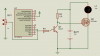
I have done a simple light dimmer project on 16f676. The program, reads a ADC channel
(Potentiometer), calculates dutycyle and adjusts the lights brightness by PWM. Since this
is probably my first project in PIC, I want to know if I have done something silly or I
have done something very awkwardly? Is there something I can do here to make it more
reliable or better?
(I have used LM7805 with decoupling caps at both input and output, for 5 V. the Power)
(Schematic is attached)
I want to use this circuit also to make a battery charger.
For this, I will be
1. Replacing the POT with a resistive voltage divider to read the battery's voltage
2. Replace the battery with the charger
3. Replace the Lamp with the battery to be charged.
What further improvements I need?
(Potentiometer), calculates dutycyle and adjusts the lights brightness by PWM. Since this
is probably my first project in PIC, I want to know if I have done something silly or I
have done something very awkwardly? Is there something I can do here to make it more
reliable or better?
(I have used LM7805 with decoupling caps at both input and output, for 5 V. the Power)
(Schematic is attached)
Code:
#include<htc.h>
//__CONFIG(DEBUGDIS & INTROSC & WDTEN & PWRTEN & LVPDIS);  // here ; must be used
#define _XTAL_FREQ 4000000
#define Out			0x00
#define In			0xFF
volatile int x=0;     // counter for PWM
volatile char duty = 90; // duty cycle set for PWM by ADC. 100 means 100 % . initial 90
volatile bit on = 0;     // flag bit used in PWM to set current state

void interrupt isr(void){   // timer0 interrupt for PWM
	if(T0IF){
    	x++;				// increment counter on every interrupt
		if(on==0 && x>=100-duty){   // switch on (if off) output as soon as x reaches (100-duty)
          on=1;						// set on flag
          x=1;						// reset x to 1
  		}
   		if(on==1 && x>=duty){		// switch off (if on) as soon as x reaches duty.
	      on=0;						// reset off flag
          x=1;						// reset x to 1
        }
		if(on) { RC3=1; RA5=1; }	// switch on/off actual output ports according to flag bit.
		else {RA5=0; RC3=0; }
       T0IF=0;						// clear interrupt flag
	}
}

void main(){

	TRISC = Out;
    TRISA = Out;
	TRISC2 = 1;  // analoge input channel an6
    CMCON = 0xff;  //disable all the comparators
    ANSEL = 0b01000000;  // disable all the analog modulse except an6
    OPTION = 0b11011000 ;// disable internal weak pullup,,internal clock source for T0
                             // ,, assign prescaler to wdt,prescaler 000
    T0IE = 1; //enable timer 0 interrupt
    GIE = 1; // enable global interrupt
    ADCON0 = 0b10011001 ; //enable adc.
// right-justified/Vref=Vdd/(Ignore)/(c1/c2/c3)channel 6/godone/adon
    ADCON1 = 0b01010000 ; //recomended value for ADC clock for 4Mhz, always use this
    __delay_ms(30);

while(1){  // main loop

int lowtot; // sum of lower 8 bits of ADC
char high;  // variable for storing upper 2-bits. bit 9 and bit 10.
lowtot=0; // initialize to 0
char samples = 50; // no of samples for avaraging
for(char i=0;i<samples;i++){
while(GODONE); // wait till finish
GODONE=1; // start ad conversion
while(GODONE); // wait till finish
lowtot+=ADRESL; // keep adding
}
lowtot /= samples;  // find avarage

duty = ADRESH*25 + (lowtot*25/255) ; // calculate duty cycle. if ADC reading is all 1111111111, then duty = 100.
// 75% weitage to ADRESH and 25% weitage to lowtot.

}

}
I want to use this circuit also to make a battery charger.
For this, I will be
1. Replacing the POT with a resistive voltage divider to read the battery's voltage
2. Replace the battery with the charger
3. Replace the Lamp with the battery to be charged.
What further improvements I need?
Attachments
Last edited:
") . I will move on to battery charger now. Will comeback with specific questions if I encounter any.
. I will move on to battery charger now. Will comeback with specific questions if I encounter any.