2camjohn
Member
I am adding a PWM battery charger to one of my circuits, im having some trouble getting the PWM to work.
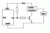
Attached is the relevent parts of the circuit, in order to make the current source high, the transistor needs to be switched off.
I have run a variety of test programs to ensure everything works circuit wise.
I have done the PWM in software, I have chosen a duty cycle of 100us, the problem is, whenever I run the PWM even at 90%, the io pin remains high (over 3V) which keeps the transistor on meaning my constant current source is always off.
(running the PWM at 100% does turn the current source on and all works fine)
I think maybe my duty cycle is too small, but before I completely rewrite my PWM code I thought I would check with you good people first.
Any ideas?
Many thanks
John