Noah_swann
New Member
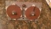
Hi all, I'm hoping you can help me out in fixing my dads old battery charger (Century 60amp 6/12v) that is circa 40 years old!
I have ascertained that the rectifier is the problem as I have 31V AC from the two wires going into the rectifier plate from the transformer, but 0.6V DC coming out. I'm aware that having 2x 6 diode plates is old school and is relatively obsolete and expensive to repair (Century have a pack of 4 diodes for $23). What can I use to bring it kicking and screaming into the 21st century and how would I go about wiring it in? (Bearing in mind I've not been involved with electronics since my high school days some 18 years ago, so I'm fairly rusty!)
If it makes any difference, I'm in the UK so the unit has 230v input.
Thanks in advance for any advice!
(Apologies if I've posted in the wrong section!)