Continue to Site

Welcome to our site!

Electro Tech is an online community (with over 170,000 members) who enjoy talking about and building electronic circuits, projects and gadgets. To participate you need to register. Registration is free. Click here to register now.

  • Welcome to our site! Electro Tech is an online community (with over 170,000 members) who enjoy talking about and building electronic circuits, projects and gadgets. To participate you need to register. Registration is free. Click here to register now.

Basic pcb repair (novice)

Status
Not open for further replies.

Bp262

New Member
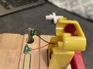
Hi all. I need help with how to fix a snapped pcb on my son's toy. It's a level crossing as part of a wooden train set - train travels over it and sets off blinking leds. The part of the board where two leds are has snapped between them.
My original thought was to solder a wire from - to- and another from + to + and glue the board back together. If so, what gauge wire? The existing wire measures ~0.7mm diameter.
Obviously any advice welcome, I really am a novice.

I've attached a photo of the broken section.
Thanks in advance!
Ben
 

Attachments

  • IMG_1142.jpeg
    IMG_1142.jpeg
    1.7 MB · Views: 217
Simply glue the board together and solder solid wires across the tracks - scrape the green resist off the tracks in order to enable them to be soldered.

Make sure you scrape and tin the tracks before you glue it together, and I would also solder the wires on one half before gluing as well, the solid wires will strengthen the glued joint as well as completing the electrical connection.
 
If you scrape the white text and green solder resist from the PCB for a few millimetres either side of the break, you will be able to see the copper track that cross the break. There will be either one or two tracks across the break.

You can glue the board pack together, using a bit of plastic or wood to reinforce the repair, on the other side of the PCB.
Then tin the ends of the broken tracks and then solder a bit of thin bare wire across each break, to reconnect it.
 
Using some quick set epoxy may allow you to strengthen the board as well. I would solder the wires across first, then epoxy over both sides, allowing for any clearance required when you mount the board back into its original container.
 
It appears that the +ve of the LED on the half of the board with the black wire was connected to the -ve of the the LED on the half with the red wire, and that that connection is the only broke one. You could just connect to the round pads (+ on the half with the black wire and - on the half with the red wire) and not have to worry about scraping the solder resist off.

Using something as a splint and glueing the halves to give mechanical strength is a good idea. The original board was both a mechanical and an electrical connector, like most circuit boards, which saved assembly time. However, you do not have to use the broken tracks on the board if you don't want to. It will be much easier to solder to the existing pads.

It's no bother scraping the resist off, and soldering solid wires along the tracks makes a decent mechanical connection as well as an electrical one, which is why I suggested that method.

I've repaired numerous broken PCB's over the decades, and this is usually the best method, and saves trying to add extra mechanical splints (although extra is always good, if there's room).
 
Thank you all for your advise. I'm going to give this a go next week. What gauge wire would you suggest? 28/30? And I assume eBay/Amazon is the best place to source this?
 
Thank you all for your advise. I'm going to give this a go next week. What gauge wire would you suggest? 28/30? And I assume eBay/Amazon is the best place to source this?

Wire similar to that on the end of resistors and capacitors, you want solid core so as to give mechanical strength.

For heavier tracks (or larger boards) I've often used the earth wire from 1.50mm or 1.00mm twin and earth.
 
Status
Not open for further replies.

Latest threads

New Articles From Microcontroller Tips

Back
Top