Continue to Site

Welcome to our site!

Electro Tech is an online community (with over 170,000 members) who enjoy talking about and building electronic circuits, projects and gadgets. To participate you need to register. Registration is free. Click here to register now.

  • Welcome to our site! Electro Tech is an online community (with over 170,000 members) who enjoy talking about and building electronic circuits, projects and gadgets. To participate you need to register. Registration is free. Click here to register now.

Basic AC motor wiring question

Status
Not open for further replies.

Jonasx

New Member
I'm brand new to electric motors and am trying to adapt a 115vac dryer motor to a screw drive application. I have the motor and after some extensive searching I found a wiring diagram that I dont quite follow. I've attached a rough reprensentaion of the scematic, can someone place the power to it and give me a brief explanation why...?


Thanks Much

Edit: Sorry for the cross post cant delete... :|
 

Attachments

  • motor_121.jpg
    motor_121.jpg
    15 KB · Views: 3,155
Looking at your drawing, is the switch shown a centrifugal switch? If it is it would have some weights that move out as the armature spins and by doing so activate the switch over from start to run.
I have no idea why there is a second contact arrangement, usually only one is required.
The start winding is only briefly connected to start the rotor up and the centrifugal switch opens the power to it once the armature is up to speed.
The start winding is not designed for longer than just a brief application (a few seconds) of power to it. The run winding is what does the work in these kind of motors.

With your arrangement the motor would only turn in one direction only, to reverse it one would have to reverse the connection to either, the start or the run winding but NOT both. For this, the connection where the two windings join (at the 'protector') would need to be able to be broken.

To connect it to the mains just do as indicated, at #1 and # 4 terminals.
 
I got impatient and grabbed the fire extinguisher and tried it, took the cover off of the switch assembly so i could see what was going on in there, that switch is indeed a centifugal switch, there is lever actuated by some spinning weights inside. Do i need to ground this in any manner? Thanks for the reply.


Edit:

I found some more info on the motor from grainger.com

heres the text

Appliance Motor, Dryer, Split Phase Open Motor, HP 1/4, RPM 1725, Voltage 115 V, Service Factor 1.00, Frequency 60 Hz, Mounting Ring, Bearings Sleeve, Thermal Protection Automatic, Full Load Amps 4.2, Rotation CW/CCW, Lead End

and a picture

https://www.grainger.com/images/products/2K015.JPG

this photo seems to have a different switch configuration than the motor i have..hmmmm...the description for this model number says its reversible..im thinking something is amiss...
 
Yes, it is always a good idea to ground the metal body of a motor once you have connected and bolted it to whatever use you are making of it.
Take care during testing, the motor will 'kick' on startup, tugging on the wiring in the process if you do that while the motor unrestrained in any way.
I'm sure you can figure out the yes or no reversing possibility from the info I gave you.
Klaus
 
Thaks for the help guys, i got the motor up, wired and installed and it working great. One more question if you have the time. As part of the same project I need the ac motor for , I have some power car seats to mount and make functional in my house.

How do I power these? I was thinking of just using a 12 volt power supply. These being DC motors (12 volt i'm assuming). Is there any special consideration you can see in doing this? I plan on using a junction type box to dole out the power to each of the motors (4 in each counting the lumbar). As these seats were kinda price I don't want to burn out the motors in them. I guess what I really need to know is how do amps relate in this application.

Any advice, no matter how elementary, would be appreciated.

Thanks
 
Jonasx said:
I have some power car seats to mount and make functional in my house.

How do I power these? I was thinking of just using a 12 volt power supply. These being DC motors (12 volt i'm assuming). Is there any special consideration you can see in doing this? I plan on using a junction type box to dole out the power to each of the motors (4 in each counting the lumbar). As these seats were kinda price I don't want to burn out the motors in them. I guess what I really need to know is how do amps relate in this application.

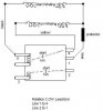
Standard auto power seats are nominal 12VDC devices, with reversing normally being handled by the switch arrangement. In most American autos, the power seat circuit is usually protected via a 20A self-resetting (thermal) circuit breaker, though I have seen some with 30A ratings.

Why don't you simply apply power to the seat motor(s) and measure the current draw? Bear in mind that the curent draw will be somewhat higher if there is someone actually sitting on the seat, so that is the best way to check the draw!

I remember a problem years ago when I was a Ford service manager. The customer, a petite woman, complained that the power seats in her new Lincoln would not work reliably for a while, and then would quit altogether. The tech assigned to the job found a failed (open) circuit breaker -- unusual, but not unheard of. The CB was replaced and the car was returned to its owner. A couple of weeks later, it was back with the same problem, same cause, same solution. This time, we measured current draw on all of the motors, and found nothing amiss, so the car was again returned to its owner. As you might have guessed, it was back a third time with the same problem. This time, the customer was making lawsuit noises -- three times, same problem etc. , and we were hard-pressed for a solution. In duscussing the problem with her at length, it was mentioned that she had no problems until the seat quit working entirely. It was her husband who was having the continual seat problems. I politely asked her if it was possible to have her husband "stop down so that I could chat with him". What I really wanted was to see him... to see if my SWAG as to the cause was right. It turned out that I was right! Her husband weighed almost 450 lbs! His weight on the seat was considerably more than the Ford engineers had anticipated, and was causing such excessive current draw that the breaker would continually trip and reset when he adjsuted the seat. Of course, this would continue until the breaker cycled itself to death. Needless to say, that was a tough one to explain in a polite manner... :)
 
Heh, hopefuly i wont have that problem. Forgive me for the obvious questions, as I'm an absolute novice in electronics. To test the amps the motors are drawing, I should:

1. Acquire at least a 12 volt/20 amp power supply
2. Wire it into my 'junction' arrangement
3. Connect all the seats motors to said 'junction box'
4. Hook the meter across the power input leads.
5. Test with the heaviest friend(s) I can find, using as many motors simultaniously as I can.
6. Make note on current drain and adjust from there?

Thanks for the help :)
 
If you know the year, make and model of the vehicle from which the seats were pulled, it would make good sense to get the seat control (switch) assembly from that vehicle. It will likely be available through a wrecking yard rather than buying one new.

Using that switch and an automotive battery (follow proper safety procedures :) ) for your power source, measure the current draw for each of the motors. Generally speaking, the switch assembly will only allow operation of a single motor at any given time. This is done to limit the current flow through the switch. Also, remember that the ammeter is to be connected in series in the circuit, unlike a voltmeter which is connected parallel to the circuit leg being measured.

I would measure both loaded and unloaded current draws for each motor, as this will allow you to build your body of knowledge. Having such measurements recorded and available may well help you later when trying to troubleshoot a problem.
 
The seats are complete with wiring and controls. My main concern was doing something to overload and burn out the motors. Is the main concern here making sure there are enough amps from the power source? I can trace the wires from the harness into the switch and out to each of the motors. So to get these up and running for testing, it should be as simple as hooking 12v to the leads into the switch and grounding the other side of the motors to the power supply, then taking the measurements? Then when buying a supply just for these seats, I should get one that exceeds the maximum draw of 2 motors running at once and wire a breaker into the circuit?

Thanks for the help
 
In any circuit, the maximum current carrying capacity of the circuit is determined by the least capable device. Consider a circuit with a motor that will draw 10 amps and a switch and wiring that will carry that 10 amps, but with a 1 amp fuse in series. Here, the fuse is the least capable device, and thus will be the determining device when it comes to circuit current flow.

In all probability, the switch assembly that you have was designed to control motor direction for the various motors installed. As such, it will have a +12VDC and a -12VDC connection. DC motors are generally direction-controlled by the polarity of the applied voltage. The simplest way to measure the motor current for each individual motor in this case is to place the ammeter in series with either the positive or negative lead to the switch -- between the battery and the switch -- being sure to observe meter polarity when doing so. Make sure that the ammeter used is sufficiently capable to handle the anticipated circuit current.
 
Status
Not open for further replies.

Latest threads

New Articles From Microcontroller Tips

Back
Top