Continue to Site

Welcome to our site!

Electro Tech is an online community (with over 170,000 members) who enjoy talking about and building electronic circuits, projects and gadgets. To participate you need to register. Registration is free. Click here to register now.

  • Welcome to our site! Electro Tech is an online community (with over 170,000 members) who enjoy talking about and building electronic circuits, projects and gadgets. To participate you need to register. Registration is free. Click here to register now.

Bandpass Filter

Status
Not open for further replies.

orlando123

New Member
How do you determine high and low cut-off frequencies necessary for a bandpass filter with a center frequency of 2000 Hz?
 
It entirely depends upon the requirements of the application where the bandpass filter is to be used. Without that information it is not possible to further answer your question.
 
The circuit contains an amplifier and a filter. I need to create a bandpass filter with a center frequency of 2000 Hz but dont know how to determine the cutoff frequencies to ensure that the center is indeed the desired frequency.
 
Maybe you are making a bandpass filter with a lowpass filter plus a highpass filter. It will have a low Q and will cut the center frequency if you try to make its Q as high as possibble which is not very high.

For a high Q bandpass filter you shoulf look in google at Multiple Feedback Bandpass Filter.
 

Attachments

  • multiple feedback bandpass filter.PNG
    multiple feedback bandpass filter.PNG
    5.1 KB · Views: 220
The circuit contains an amplifier and a filter. I need to create a bandpass filter with a center frequency of 2000 Hz but dont know how to determine the cutoff frequencies to ensure that the center is indeed the desired frequency.
By definition the center of a bandpass filter is the center frequency.

A bandpass filter has a center frequency and a bandpass width. The upper cutoff frequency is 1/2 the bandwidth above the center frequency and the lower cutoff frequency is 1/2 the bandwidth below the center frequency.

You need to know what bandpass you need, along with the center frequency, to design the filter. You also need to know how rapidly the filter needs to roll off at each cutoff frequency (determined by the filter order).

I believe you need to do some study on how filters work.
 
Yes, by incorporating a lowpass filter and a highpass filter to create the bandpass. If bandwidth can be any length, how do you keep the center frequency at 2000 Hz?
 
Here is how I would do it ;)
 

Attachments

  • FiltPro.png
    FiltPro.png
    31.9 KB · Views: 168
Yes, by incorporating a lowpass filter and a highpass filter to create the bandpass. If bandwidth can be any length, how do you keep the center frequency at 2000 Hz?
By definition it's half way between the lowpass roll-off and the highpass roll-off.

Why is that confusing?
 
Yes, by incorporating a lowpass filter and a highpass filter to create the bandpass. If bandwidth can be any length, how do you keep the center frequency at 2000 Hz?

Hi there orlando,

There are quite a few different ways of doing this filter, so we need to know a little more about what it is you are trying to do and what restrictions might apply as to how you can do it. For example, do you really have to use two separate filters (low pass combined with high pass) or can you use one single filter. Also, can you use an active filter (contains an op amp) or do you have to use passive filter(s) (contains only resistors, capacitors, and possibly inductors)? Another thing we would have to know is what kind of power supply rail(s) you have available, for example do you have plus and minus 15 volts available or not? Also, how selective does your filter have to be?
We have to know these things first to find the best filter for you.

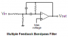
A good example of a modern bandpass filter is the one posted by audioguru, but again we dont know yet if you can use an op amp with your design. The design formulas are as follows:
R1=Q/(G*2*pi*f*C) [input resistor]
R2=Q/((2*Q^2-G)*2*pi*f*C) [one side grounded resistor]
R3=Q/(pi*f*C) [feedback resistor]
where
Q is the desired Q of the circuit (equal to center frequency divided by the bandwidth),
G is the required passband gain,
f is the center frequency (2000 in your case),
C is the capacitance of both C1 and C2 (both caps, for example 0.01uf each).

To use those formulas you pick a value of C say 0.01uf and a value for Q and a value for the passband gain G. Q affects the sharpness of the filter, G affects the gain at 2000Hz.
Since those formulas are for a circuit containing a perfect ideal op amp sometimes you have to adjust the value of f a little bit to get a better circuit for a real life op amp ie making f equal to 2050 would probably get you closer to the actual real circuit for use at 2000Hz. In any case however it's a good idea to do a simulation before deciding on the final values.
Note that the bandwidth is the two sided bandwidth so for example with a center frequency of 2000 and bandwidth of 200 that would mean 100Hz on either side of the center frequency to the -3db point. Since Q=f/bandwidth that means Q=2000/200=10 for this example.
 
Last edited:
Status
Not open for further replies.

Latest threads

New Articles From Microcontroller Tips

Back
Top