Continue to Site

Welcome to our site!

Electro Tech is an online community (with over 170,000 members) who enjoy talking about and building electronic circuits, projects and gadgets. To participate you need to register. Registration is free. Click here to register now.

  • Welcome to our site! Electro Tech is an online community (with over 170,000 members) who enjoy talking about and building electronic circuits, projects and gadgets. To participate you need to register. Registration is free. Click here to register now.

Axial RF Choke Inductor???

Status
Not open for further replies.

AtlasRucker84

New Member
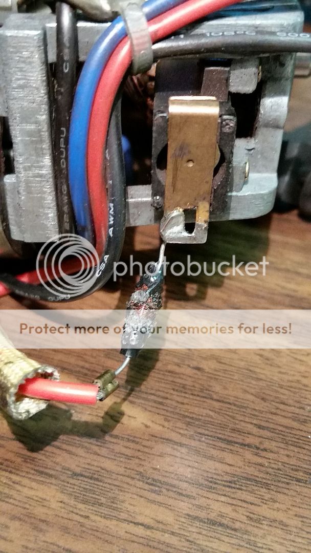
I need help with this. I am not educated in electronics, but know enough to get by with basic repairs or etc. So the other day I burned up something that probably is not worth my time fixing, but I figured, hey might be something simple, a thermal fuse on the motor windings. I knew it was going to be more then a common fuse, as it had that distinctive odor to it. So I get into it and rip the whole damn thing apart. So I get the guts of the thing and the motor windings and circuit board are intact, presumably. Then I look at the back of the motor and off the electrical bushing there are two components in series on both the positive and neutral sides. Sure enough they were burnt to a crisp. The only problem is I have no idea what they are or what the ratings would be for replacements. From what I can gather they are axial RF choke inductors. Which is in itself is puzzling to me. Why not capacitors or resistor capacitor combo? Why use a RF inductor opposed to some other EMI noise reduction, assuming that's what they're for?

Some info:
12v axial shaft high torque motor
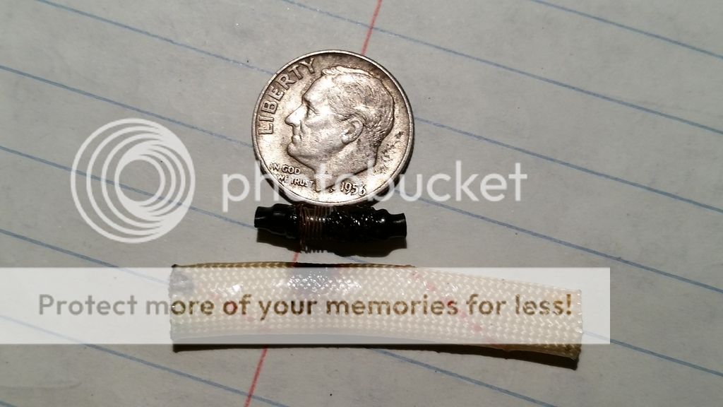
Inductors???:
4 turn per mm

28 turns on the bottom
10 turns on top layer
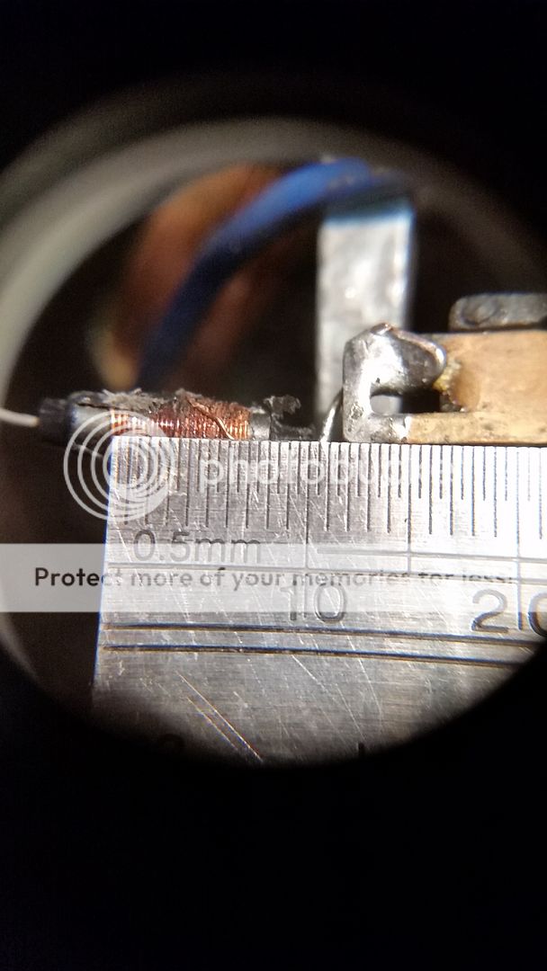
3mm Dia. ferrite rod core by 10.15mm in length

0.30 mm (according to my digital gauge) so roughly 29 Gauge copper turnings.

20151009_1142391_zpsguvnhnnc.jpg


20151009_1158311_zpspmhpxnf5.jpg


20151009_1306141_zpsyh9lqxhk.jpg
 
Why not capacitors or resistor capacitor combo? Why use a RF inductor opposed to some other EMI noise reduction, assuming that's what they're for?
The common expression for that component is an "RF Choke".

Resistors would be a bad idea to put in series with the motor because they have, resistance, and resistance will drop voltage and reduce the volts available at the motor, so reducing the power/torque which the motor produces.
The RF choke has very little resistance so the volt drop is not a problem.

Why not use capacitors?
There are often several ways to fix a problem.
Assuming that the original designers of this motor did a proper job, they probably found that the little chokes did an adequate job of supressing RF noise produced by the motor, and a choke is inherently more reliable than a capacitor and probably cheaper.

So why are your chokes burned to a crisp?
Presumably the motor is faulty or has been overloaded and a high of current has flowed through the chokes, and even though they have very little resistance, there are limits to all things and these have been pushed too far.

JimB
 
Wow, you should hang on to that dime, it is a silver coin (pre-1964). Worth a few bucks:)
 
It would be easy to make/wind a replacement, usually they are not that critical for the overall operation, they do look underated to me for that apparent size of motor.
Max.
 
I am sure as Jim eluded to, most like something going on to blow up the coil.
 
Could it be as the motor is straining with achieving proper torque that it is trying to draw to much as thus over-loading the coil? I know that this is only a 12v DC motor, but the thing is geared up even after that for a lot of torque. I am wondering because of the gauge of wire used, if that wasn't engineered as a sort of dumbed down thermal fuse of sorts and hence the thermal wire sleeve? If that be the case it would be sort of really dangerous in its current application. But, that would be Chinese engineering. Further research into this has proved that at some point the company was made aware of the unit's tendency to over heat and over-draw. I could not find anything on the circuitry of the unit as it is probably a state secret and property of the Chinese Government. The new motor seems to have greatly improved with better brushes and even a built in cooling fan to boot!

I am looking at the following as a replacement. But this is where I know absolutely nothing about loads or etc and look to a community of experts and/or subject knowledgeable peers for help.

40uH 20% Axial RF Choke Inductor RCW0520U-400M-032-L

https://www.westfloridacomponents.com/IN027/40uH+20%+Axial+RF+Choke+Inductor+RCW0520U-400M-032-L.html

I am not sure where my endearment for these old machines, tools and other widely collected/hoarded items comes from.
20151009_202825_2_zpsb2n3fyxh.jpg


Or why I have become strangely fixated on fixing this thing, when I probably could have scrapped it and bought a new one for less then 200$. And saved a week of researching, but where is the challenge in doing that?

Nothing ventured, nothing gained. Plus I would rather spend $0.66 and burn the windings or the board up then say I didn't try....

Just realized that coin above say In COD we trust... Love a good game of Call of Duty. And speaking of duty.... just realizing now that 20% for the choke may be referring to a duty cycle....
 
Last edited:
Status
Not open for further replies.

Latest threads

New Articles From Microcontroller Tips

Back
Top