Continue to Site

Welcome to our site!

Electro Tech is an online community (with over 170,000 members) who enjoy talking about and building electronic circuits, projects and gadgets. To participate you need to register. Registration is free. Click here to register now.

  • Welcome to our site! Electro Tech is an online community (with over 170,000 members) who enjoy talking about and building electronic circuits, projects and gadgets. To participate you need to register. Registration is free. Click here to register now.

Automatic rear spoiler project

Status
Not open for further replies.
Also beware that depending how big this thing is at 60mph the force might be substantial, you'd need something way more powerfull than a wiper motor to shift it, more along the lines of a power jack.
+1 May also bend or distort the frame of the thing.
 
The operation is a bit more complex: See PDF page 5: http://www.google.com/url?sa=t&rct=j&q=&esrc=s&source=web&cd=3&ved=0ahUKEwi-7KzigP3MAhUYSFIKHYMBDc0QFgg6MAI&url=http://srt-6.com/pdf/tsb/SB_23_040_04_Spoiler.pdf&usg=AFQjCNEYIaJ9HJGMsmJw2A1Sz-
34W9ZbPw&cad=rja


It exerts 40lbs of downward force at 63 MPH, so a pretty beefy motor. gearing.

OPERATION
The rear spoiler is powered by an electric motor
located directly below the spoiler wing in the spoiler
assembly. When the vehicle reaches 62 MPH (102
km/h), the rear spoiler deploys, giving the vehicle 40
Lbs. (356 Newtons) of downforce at 80 MPH (129
km/h). As the vehicle decelerates, the rear spoiler
starts to retract at a speed of 39 MPH (62 km/h). When
retracted, the spoiler nestles between the rear quarter
panels and the rear liftgate window.

The spoiler can be manually deployed at lower speed
using the override switch mounted in the center
console. Pushing the switch up raises the rear spoiler.
Pushing the switch down lowers the rear spoiler.

To prevent injury, the rear spoiler retracts in defined
steps to allow time to pull any hands or foreign objects
that may be in the path of the rear spoiler before it is all
the way down. If the rear spoiler gets disturbed while
retracting automatically or while retracting manually,
the rear spoiler is automatically driven up again and will
lock in the up position.

During manual retraction, if you
let up on the switch, the rear spoiler will be driven to its
up position. When retracting the rear spoiler manually,
a single audible chime is produced to indicate to the
driver that the rear spoiler is in the fully retracted
position.

A warning signal (LED) on the spoiler override
switch illuminates, indicating a malfunction to the driver.

A malfunction that prevents the spoiler from deploying
illuminates a red warning lamp in the override switch

I'm having a hard time understanding the last two sentences. I separated the paragraphs along the way from the top.
 
The spoiler mechanism is likely do serious damage if "things" get caught, so "automatic" has to be really taken seriously and the OEM does,

This https://www.pololu.com/product/708/pictures from Pololu (the VN2) version does offer the ability to be able to current monitor, so it COULD be a viable motor driver.

At this point, I think it does require a micro-processor primarily because of the step nature of the beast. It wants to move it a bit, so hands could now move out of the way. The mechanism has the potential to do some serious damage.

This is no longer a simple Motor-limit switch deal or even an automatic up/down deal. It's a can or arm crusher kind of deal. The OEM even employs the protection in manual mode. <39 (close) and >63 (open) ONLY is likely people/objects safe when do motor protection is employed, but it may not be safe from itself. Ice/snow comes to mind, but that likely doesn;t occur in California. The safest position is UP.
 
40lb is that all, thats not going to improve handling much, more of an ornament.
 
Diver300. Very nice find. I registered and they show prices. Probably around $100.00 USD give or take. The Chrysler model wasn't listed, but that doesn't mean much. Sent an email about what the pulse output circuit looks like.
 
Double Wow! I've not received any notices that there were any more replies since spec's comment 05/26. I'll admit that the opening and closing at fairly specific speeds is something I'd really like, but not at all as important than conveniently raising/lowering the spoiler. As far as using the BCM, it appears as if there isn't any spoiler info. I got brave and hooked up the spoiler/motor directly to the battery, and it goes up nicely - though I didn't run it very far/long. I felt the close-up on the little black box (there's also one on the other side) next to the gear might be important. Could they be the limit switches? There are three pins for them. Each have the a common black wire and one uses a blue and the other is white(?). FWIW it turns out that the brown wire to the motor is ground and the black is +. Keep in mind I do have a full set of service manuals, so possibly these 'units' might have a diagram. I believe the photos should be pretty self explanatory. Do you all prefer full size or thumbnail?

SRTXFSpoilerPickUp.jpg
 

Attachments

  • SRTXFSpoilerUp.jpg
    SRTXFSpoilerUp.jpg
    83.2 KB · Views: 193
  • SRTXFSpoilerUpB.jpg
    SRTXFSpoilerUpB.jpg
    67.2 KB · Views: 200
  • SRTXFSpoilerDown.jpg
    SRTXFSpoilerDown.jpg
    74.9 KB · Views: 202
  • SRTXFSpoilerArms.jpg
    SRTXFSpoilerArms.jpg
    82.7 KB · Views: 195
  • SRTXFSpoiler6.jpg
    SRTXFSpoiler6.jpg
    92.5 KB · Views: 199
The limit switch is depicted in your pic in post #2: https://www.electro-tech-online.com/attachments/xfspoilerdiagc-jpg.99715/

It most likely connects to ground at a limit. Needs to be checked.

The OEM switch also appears to have a LED. I didn't see anything showing that.

There is a resistor in the OEM dash switch. It should be measured. The switch seems momentary.

"current draw" is another helpful number. At least the order of magnitude.

If you don't visit the thread after you get a notice (i.e. you just read it in your email) you may not get more notifications.

At the top of each thread, there should be a "watch thread" and or "unwatch thread" link. It's generally useful when you want to monitor the progress of a thread but don't have anything to post yet.

It's not the speed of the raising, but more of a "notice". i.e. If the spoiler suddenly moves a bit, then a person knows to get out of the way. I suppose it also does that just to see if it isn't frozen shut. Not a problem in CA.

The motor should not have a common wire. You have to have independent access to move it up or down.
 
Measuring across the diodes, I can't get a reading. The left number is 679. I would be very uncomfortable if I need to get to the back of the circuit board. My rather inexpensive multimeter is perhaps not sensitive enough? Also I've never needed to measure a diode before.

I have no idea how to get a current draw. Obviously this switch is loose. The one in the Ltd. would be a nightmare to access. I did include a Rear Spoiler Inoperative diagram that shows there being 5 Volt coming from the BCM to the rear spoiler switch - if that helps.
XFSpoilerSwtchDiodes.jpg


I did not say the motor had a common wire, but the two gizmos have a common black wire. I'm surprised that no mention was made of the gizmos.

I'm not trying to be difficult here, but you're really talking to a guy who knows absolutely nothing about electronics. I'll add that who is very good at making cold solder joints.

When the spoiler is fully extended it stops short of being past the rear bumper.

Not my idea to put the photo in the middle of the copy. Still learning.
 
Are their any components on the back side? Schematic showed at least one resistor.

Does your meter have a "diode" or continuity mode? Just asking. The diode mode usually beeps when the leads are shorted together.

The LED could have a built in resistor or the resistor could be sized for 12 V or 5 V.
 
Yes, the meter does have a diode setting and there is a beep when I touch the leads together. But no movement on the meter when I touch the two raised posts on either side of the diodes.

Looking down the center of the underside it appears as if all there is are the soldered ends of the diodes and LED. Access to the the backside would include Dremeling off a portion of the clip which holds the two pin plug in place before I can access the underside of the circuit board.

I'm purely guessing that the 5 volt to/from the BCM is because it's merely sending a signal. The very short time I ran the motor with 12 volts, nothing indicated there was any problem with it.

Unfortunately I have the feeling that it might make more sense to just use a single pole double throw momentary (normal) switch.
 
They should be a tact switch, I think. Push on them and they should make a tiny click.

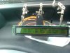
So, I see two switches and an LED.

This https://www.electro-tech-online.com/attachments/xfspoilerdiaga-jpg.99712/ diagram of yours shows two switches and a resistor.

Something does not add up? Wire colors?

From what I see in the picture, I imagine a 4 pin connector on the other side.
One pin should be common. Call it PIN C
Pushing on switch A should connect/disconnect say PIN U
Pushing on switch B should connect/disconnect PIN D
The leftover pin should connect to say PIN L.

Using, Up, Down, Common and LED.

If you look at this https://media.digikey.com/PDF/Data Sheets/Everlight PDFs/ds300016.pdf datasheet and look carefully, you will see a flat side on the LED.

That is the negative side of the LED. If you use you meter in continuity, you should have 2.1 when the neg probe is on the flat side and the positive probe is on the other.

When you flip the leads, you should have nothing.

There's always a couple of gotcha's. The LED needs a resistor. That resistor for the most part determines it's operating voltage. It COULD be inside the LED. In a mass produced car, I would suspect not. It could be on the PCB or it could be in the BCM. In reality - no big deal.

The bigger deal is where the flat end goes? Is it common?

If you have the connector, do the wire colors match the schematic?

So, a resistor exists, like in the schematic for the switch or you have the wrong schematic.

another resistor could exist for the LED on the switch.

So, pick a pin and using continuity find an arrangement that you get (push U = beep), (push D = beep ), ~2.1 on pin L with one pin common. Where is the neg probe?

If you don't get two pins with a beep, then one pin may have a resistor to common.
 
I'm going to have to get back to you tomorrow. I'll dig out my 12 power engraver's glass and see what I can come up with.
 
The "minimalist", "effective", "least expensive" solution I still see is:
1) Relay based
2) LED off when fully up or fully down. LED on when between limits.
3) Limit switches will work.
4) Use original momentary UP/DOWN (EXTEND/RETRACT) switch
5) A "fuse" sized for overload protection.

(5) is generally not a design goal because people can put the wrong fuse in.

The "side effects" would be that the user would have to not change direction rapidly or pulse the switch rapidly to avoid blowing the "fuse".

LED blinking while the motor terminals have power MIGHT be worth investigating.
 
I did some more searching and came across this **broken link removed** thing.

It seems overkill in some ways and underkill in others, it looks like it has the ability to be in a car environment, small size, has stall and limit capabilities and at least has an output that could be used to drive an LED. It's scrip-table. "glue logic" and wiring is still needed.

It's not a general purpose controller an it doesn't support strings except for debugging. I don't know how well it would play with a "speed interface". The speed to analog converter might work.

So, this might be how I might design something. Get a price for the speed to analog converter and use a product that could support it. It's even possible that the code could be written to support the interface, just not enabled.
 
I dont know how much electronics knowledge you have, however obd2 is not difficult to get speed data from, there are dongles that communicate to most vehicles available that convert the cars protocol to rs232, I made this a while back, it displays a few engine parameters, aquiring speed data and controlling a servo are not hard to do with an arduino, this particlular circuit uses a pic:
Servo objects and obd objects (pre written sections of code) are allready available.
 

Attachments

  • Picture.jpg
    Picture.jpg
    1.6 MB · Views: 191
Kinda.
I used a cheap import dongle, it came as a obd2 to usb interface, I removed the ftdi chip and put a 9 way D on the end wired as 5v rs232.
 
SDC2160 appears to be interesting, but where would the initial signal originate? Have 'we' agreed that the two gizmo's on either side of the plastic gear are in fact limit switches? Could they be (though I strongly doubt) switches for the opening and closing of the spoiler?

Going with their being limit switches, each having two wires, one being common; also going on the basis of using the stock dash switch (two wires) which is only able to send a signal (does it take 5 volts to send a signal?); what else do we need to 'just' raise and lower the spoiler (motor - two wires) - and - how would it all be connected (wired)?

I could see where it most likely would be important to know how the switch is set-up'.
 
Status
Not open for further replies.

Latest threads

New Articles From Microcontroller Tips

Back
Top