Continue to Site

Welcome to our site!

Electro Tech is an online community (with over 170,000 members) who enjoy talking about and building electronic circuits, projects and gadgets. To participate you need to register. Registration is free. Click here to register now.

  • Welcome to our site! Electro Tech is an online community (with over 170,000 members) who enjoy talking about and building electronic circuits, projects and gadgets. To participate you need to register. Registration is free. Click here to register now.

Automatic rear spoiler project

Status
Not open for further replies.
The simple method explained. (The LED and switch are somewhat unknown)

Take a look here: http://www.robmeyerproductions.com/bows.html at the first figure. I don't LIKE it, BUT it gives you an IDEA how things COULD be wired. In that diagram, the limit switches are INDEPENDENT which is not your case and the motor moves with a low current signal. Protection diodes are not in place either. The important thing is that the limit switches don't carry the full motor current. That wiring diagram SUCKS!

Your wiring would look MORE LIKE this
diagram.

The "SPDT" Automotive relays are available in a dual configuration with plugs and wire leads. e.g. **broken link removed**

When your finished wiring the contacts, you have a relay for up and one for down. Because the motor is shorted with both off or even both on, the motor stops instantaneously.

Now, your choice if you want common + or common negative.

NO LIMITS yet. SUPPOSE the limit switches close on UP and close on DOWN and have a common terminal. So, you want to wire the limit switches so that they activate their corresponding small 12V DPDT relay such as http://www.digikey.com/product-deta...mfield-relays/9-1462037-9/PB1181CT-ND/1828471
So, with 12 V common to the small relay and the coils going to ground via the limit switch, we now have 2 independent contacts.

We wire one set of the independent contacts such that the EXTEND relay is not allowed to extend if the EXTEND LIMIT relay is activated. We do the same for retract. These little relays activate when they are at their corresponding limits and one of their SPDT contacts won't allow (Opens) the EXTEND or RETRACT signal to get through to the other relay.

So, we have a set of SPDT contacts left. We arrange these in parallel like an OR Gate, so you get a single contact that's closed when the motor is not at either limit. So, we can arrange the contact (direction and appropriate resistor) to activate the LED when the motor is somewhere in the middle.

We can ""play a game" and but a full wave bridge rectifier across the motor and power that LED from the motor power. Now if the motor fused blew (sized to protect) there would be no power to activate the LED when the spoiler is in the mid position.

So, you would have a small fuse for "logic power" and one for "motor power".

Your window motors might use a PTC thermister wired i contact with the motor. They have to be sized right. See: **broken link removed**

This method really doesn't have the protections one might like to see. If a fuse blows, you won;t be able to reverse the motors without changing the fuse.

You could have a different fuse for forward than you have for reverse.

"Reverse biased" diodes should be placed across the relay coils.

Hey spec, wanna draw it?

Automotive quality relays could be used: http://www.omron.com/ecb/products/pdf/auto_glossaries.pdf

The Bosch relay datasheet is here: http://www.te.com/commerce/Document...DocNm=V23234-X0000-A001&DocType=DS&DocLang=EN

The coil is about 85 ohms, so 12/85 is about 140 mA. This may be too much for the tact switch to handle. We will have to work on that one. See: http://www.digikey.com/product-deta...switch-switches/1825910-7/450-1804-ND/1731414

which is rated for 50 mA, so the OEM DASH switches WON'T work!

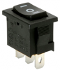
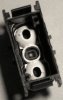
An SPDT center off switch would work.

I can "fix" it so the OEM switch works, but really need to know how it is wired.
 
Last edited:
BibaResto said:
<snip>

Going with their being limit switches, each having two wires, one being common; also going on the basis of using the stock dash switch (two wires) which is only able to send a signal (does it take 5 volts to send a signal?);

I could see where it most likely would be important to know how the switch is set-up'.

Problem:

A: possibly 3 wires just like an SPDT switch

B: Also possibly 2 wires for 3 positions. This is a lot like how the steering column switches work in a car. Different resistances are switched in depending on the switch. The diagram shows a resistor and ground.

C: LED may also share a pin or could be separate.

So, it's IMPORTANT!

the OP/TS said:
what else do we need to 'just' raise and lower the spoiler (motor - two wires) - and - how would it all be connected (wired)?

OP = Original Poster or TS = Thread Starter

Electronically, FWD, REV, coast and brake are done with an H-bridge curcuit,

https://en.wikipedia.org/wiki/H_bridge

Two SPDT automotive type relays can create a low current signal (150 mA) to say control a 10 Amp motor. You end up with a truth table of:

A B
0 0 brake
0 1 Fwd
1 0 rev
1 1 brake

These limit switches can't handle the full motor current. The TACT switches can't handle the larger relays.

I don't have a decent CAD program that I know how to use.

the nagging questions:

1) How is OEM switch wired?
2) Idea of motor current
3) Idea of time to raise/lower
4) Verification that limit switches close on limit (I'd say 99% true).
 
SDC2160 appears to be interesting, but where would the initial signal originate?

The gizmo is a motion controller. It has a small amount of user FIRMWARE that can be set to execute when powered up.

The motor connections is a given. Motor current monitoring is a given.

The CW and CCW limits have to be digital inputs.

the LED and Chime have to be digital outputs.

the UP/DOWN switch can be an analog input or 2 digital inputs.

Speed would have to be an Analog Input. Still working on it.

I/O is at a premium. If you don't need any more then your good to go. I have no idea if you can expand via CAN. String functions are not allowed.

Some of these inputs have to be interrupts. Engine running is a possible input and so is E-stop. A status LED is possible output although you can spit stuff out on the USB bus.

So, it's highly probable that this could control the spoiler with minimal "glue". "Glue being external components. It would be able to do everything EXCEPT deploy the spoiler during an ABS sensor slip. Yep, that's another way to deploy.

At least that's a first pass read.
 
This video is of a Ltd. Crossfire Roadster. I belong to the Crossfire forum and there is a fellow who has Miata with a Crossfire spoiler. Only problem he bought it that way and doesn't have a clue how it is wired. I worked with one of the members to see if an AutoLoc electric window unit (no motor) would work, but it wouldn't open the spoiler.

I'll add that no one knows why the spoiler lower's in steps.

I somewhat feel you are over thinking this project, but at the same time I appreciate your willingness to try to make it as bullet-proof as possible. I'd hate to have a set-up that sort of works sometimes, but not others.

I hope you realize I have no idea what a brake system has to do with any of this or what CW and CCW are., etc., etc.

Info for the SPDT switch: Miniature rocker switch. Specifications: • Current rating: 10A @ 125 VAC, 6A @ 250 VAC • Housing dimensions: 18.4 mm L x 12.9 mm W x 13.8 mm D • Contacts: 3 • Approval: UL.

It possibly could be installed inside the Crossfire spoiler switch's housing - if that helps at all. There would be no LED, but not sure how critical that really is.
 

Attachments

  • SRTXFSpoilerSwtch6.png
    SRTXFSpoilerSwtch6.png
    37.8 KB · Views: 207
  • SRTXFSpoilerHousing6.jpg
    SRTXFSpoilerHousing6.jpg
    37.3 KB · Views: 190
Biba:

I always overthink. A Automation professional publication (Intech) actually had an article about the method. It works well, but it's not liked by the boss because he doesn't understand it. So in the method, you try to come up with possibilities no matter what the cost, so you know what's possible and you then refine or eliminate them. Trust me, it works.

We still don't have a full deck:
1) Motor current approximate.
2) Spoiler switch wiring.
3) Find the LED and switch in the service manual.

the OP said:
I'll add that no one knows why the spoiler lower's in steps.

it's checking for obstructions and "blowing it's horn" so to speak.

I do. It was documented in the real documentation somewhere. Suppose you were leaning on it. The "spoiler" moves a little bit. You move out of the way. Spoiler and hand are both happy. The "moving a bit" is like a horn.

or suppose you were leaning on it. Spoiler decides to retract or extend. On extension, it knocks you on the ground. On retraction it traps the arm.

On retraction, if something gets in it's way, it's supposed to reverse it's direction and extend.

Up is really considered the safe place to be. Down squishes things.

So, your stopped in the driveway and some kid has their hand near the spoiler. You lower the spoiler and don't notice the kid. Kid's arm get squished.


Brake: Specifically dynamic braking. When a motor with brushes is turned without power, it acts as a generator. When the generator operates into a short, it tends to resist movement or stops.

Overrun: Brushed DC motors coast when you turn the power off, so when it hits the limit it tends to go a bit further than intended. Dynamic braking (in this case shorting the motor) stops the motor closer to instantly.

You do know what CW and CCW is. When applied to a motor context, it's Clockwise and Counter-clockwise.

There's a bunch of synonyms like CW, CCW, Retract, Extend, Up, Down. It's not likely for me to be consistent initially.

The switch does not have a DC rating. Switches can fail if not used for the proper purpose or be of the proper design.
When they are used at logic levels, the contacts are usually precious metals. If the switch develops an oxide when operated at very ow currents, it doesn't work as a switch any more. Contacts that "wipe" themselves kinda use very fine sandpaper on themselves each time they switch. If they SNAP, they may be appropriate for AC only.

Yep, I took a simple concept of a switch and made a mess out of it. I can also tell you that waving a wire in the air generates a current because it's a wire in the Earth's magnetic field. Usually no one has to worry about such things except me. The fan would cause 10's of Pico amps to be generated in the moving wire in an environmental chamber. That was the order of magnitude that I was trying to measure.

Automation is primarily a safety issue. If the spoiler resists 40 lbs, it's at least has 40 lbs of force that it can generate. That's heavy and damaging.

I've been busy overthinking.

The all in one device that can do comparisons, analog output and frequency output for 4 CAN variables is just shy of 2 killo-bucks, but it's not the only option.

Honestly, if you can't figure out the switch, send it to me. East Coast US.
 
From an NKK switch brochure:

Electrical Capacity
(Resistive Load)
Power Level (silver): 6A @ 125V AC & 3A @ 250V AC 4A @ 30V DC for On-None-On;
3A @ 30V DC for all other circuits

Logic Level (gold): 0.4VA maximum @ 28V AC/DC maximum (Applicable Range 0.1mA ~ 0.1A @ 20mV ~ 28V)

Logic/Power Level (gold over silver): Combines silver & gold ratings Note: Find additional explanation of dual rating & operating range in Supplement section.

So, a logic level power rating for this type of switch wants to see at least 0.1 Amps. The spec also says that there will me a 20 mV drop. 10 mA is usually typical, so their could be a problem with this datasheet.
 
I hung out for a while on the other forum. They gave me a nice lead which I turned into this http://www.lingenfelter.com/product/L460260704.html lead.

This is essentially has the capabilities of the device I saw for about 2 kilo-bucks and at what I would consider the right price point to at least be able to attempt a speed deployed/retracted spoiler. The device I found was more plug and play,

This and dr. Pepper "suggests" that one could roll their own as well starting with the interface.

Aside from the "hidden" CAN bus connector, someone has to "play"or interact with the OEM or the "player" may have to buy some development tools to monitor the CAN data.

Since CAN is a bus, bubble gum and paper clips are not allowed: **broken link removed**

If i remember right, the spoiler deploys automatically at 6? MPH and retracts at 3? MPH UNLESS it was manually deployed. from instructions: If the switch is depressed until the spoiler is fully retracted, a short beep will be heard, and automatic control will be
reestablished.

My alternate was a this CB-6 http://sailesmarketing.com/shop/can-bus-interfaces/cb-2-can-bus-interface/ which is plug and play ffor the Crossfire for a frequency VSS signal. It's available from: http://www.vtstore.co.uk/electronic-interfaces/cb-6-canbus-interface
So say less than $200 USD.


F to V conversion possibilities:
**broken link removed** (about $300.00 USD)

or this $20.00 USD
http://www.newegg.com/Product/Produ...GoogleMKP-PC-_-pla-_-Gadgets-_-9SIA7BF34K1338

might even work. The latter requires support electronics.

I'm also trying to "glue" this project together instead of doing it from total scratch.

Now, lets say that there's some muddy water here too. How one gets from a 1 pulse per mile VSS signal to either an analog signal ORa digital signal based on the setpoints depends on a lot of things.

Sparkfun doesn't make the comparitor kit (breakout) available any more, but it explains the process a bit. http://www.sparkfun.com/products/retired/10101

In closing this post. the automobile environment is rather hostile. See http://www.littelfuse.com/~/media/e...utomotive_tvs_diodes_application_note.pdf.pdf for just how nasty it can be.

It does mean that one should not electromagnetically pollute the environment (EMIT), but the warnings may be too excessive for a modern vehicle. Linear Technology does make some Integrated Circuits that specifically deal with surges. http://cds.linear.com/docs/en/product-selector-card/2PB_surgestoppers.pdf

It appears that the other forum www.crossfireforum.org 's member can't figure out how to incorporate the limit switch. At this point in time, it's easy to do if a more standard SPDT switch is used. A switch containing an independent LED may be findable.

In a total manual control without protection:
I'm proposing an alternate use for the LED: To have it be on if the spoiler is not fully deployed AND the motor is moving.
This basically means push the retract/extend button until the LED goes out instead of a chime. I have not been considering the chime.

If you have an alternate idea - suggest it.

Thermal motor protection can be a two-edge sword. Stay tuned.
 
Biba: RE: Spoiler dash switch

1) How many pins on the connector for the switch? I see 4, but could there be 6.
2) Locate the connector in the service manual - post the page
3) Locate the LED that;s in the switch - post the page

The pins shown for the spoiler switch are pins 2 and 6.
a) When you push up, the resistance between pins 2 and 6 should be near 0
b) When you push down, the resistance between pins 2 and 6 is? _______ I suspect below 1000 ohms.
 
The Crossfire spoiler as I understand it and some suggestions for control.

Real motor control adds safety. Using the dash switch adds esthetics's. Speed activated adds coolness. I don't like the lack of safety. A chime incorporated in the OEM controller as well indicates when manual control is restored.

1) It's easy to incorporate the limit switches with a standard (non-OEM) SPDT dash switch. With or without an LED.
2) It's highly likely that I could incorporate the OEM dash switch but need some info;
3) A RoboTeq controller ($300) designed and packaged for the automotive environment could implement safety and speed. Inputs are rather limited and there may not be enough INPUTS/OUTPUTS.
4) Something like the Coridium SuperPro and a Pololu motor driver could be cheaper if you just include parts and there are eonomies of scale to be realized.

Options (3) and (4) are open to speed controlled deployment and could be added later.
In my mind, I went full circle on options.

https://www.lingenfelter.com/product/L460260704.html essentially offers nearly all of the features of the Racelogic DAC01 and even some different ones like PWM for driving gages at what I would consider a much better price point of $289.00, but it could cost more than that.

The $120 adder for specific support or the necessity to send data obtained to the manufacturer of for the device differently to get the parameter you want for speed.

Racelogic, the really expensive interface, is geared for racing and is more definitely plug and play.

These units get the signal from the CAN bus and re-create it to another form such as Analog and what appears to be a 1 pulse per mile universal signal which seem to be used my GPS systems. Both of these CAN devices can create logic signals like greater than x MPH etc.

Apparently (best guess), there is a certain amount of data that continually gets spit out to the CAN bus, so the interfaces don't request, but rather monitor. The CAN bus for the Crossfire is not on the OBDII connector, but rather the engine compartment.

VSS or (Vehicle Speed Sensors) are all over the map. Around 4000 pulses per mile are common.

There is a guy with a Mazda Miata that put one of these spoilers on his vehicle and wants to do the speed thing too. That vehicle may or may not have CAN and I haven't made myself known on that forum.

No one has been able to incorporate the limit switches or the OEM switch. I don't have enough info for the OEM switch, but I looks like it could or does create 0 V, 2.5 V and 5V, or something similar, levels for UP/DOWN and OFF. The OEM switch has a LED, but I have not found all of it it in the wiring diagram. The LED side is missing. To cut down on the mumber of wires in the car, a resistive method to get 3 states from 2 wires is used.

It seems as if an external pull down was used at the same unknown value of resistance un the OEM switch, you could end up with 0, 2.5 and 5V. So, the OEM switch configuration is a UNKNOWN. The LED configuration is an UNKNOWN.

For the manual only options, I'd consider re-purposing the LED. It could illuminate when the spoiler is in between positions AND the operator is trying to move it. I think the OEM idea is to keep the operators eye not on the switch while moving it.

So the automatic spoiler extends at 62 and retracts at 39 mph.

If you retract it manually, it should chime when fully retracted. My guess is, that if the spoiler is manually deployed at any time, it should stay deployed, possibly through car starts. Only when it's fully retracted and a chime sounds will it resume automatic mode.

The OEM spoiler moves in about 5 discrete steps checking for obstructions in between. It essentially "blows it's horn" or says "excuse me" when it moves a bit to tell "people" that they are in it's way. The spoiler takes about 5 seconds to move from one extreme to the other.

The automatic control has to be held down until it's fully retracted (chimes), otherwise it reverses and returns to extended (The safest position).

I don't know if it's possible to “fake” a chime. e.g. temporarily create a condition that generates a single vehicle chime or an external chime generator needs to be used.

“Spoiler up” appears to be momentary and will auto-complete the move. Auto-spoiler is enabled once the spoiler is fully retracted manually. The spoiler won't sit in between positions unless there is a really hard fault like “can't move”. e.g. If “going down” automatically or manually and it encounters an obstruction, it switches direction and goes up and probably sets a fault.

I'd assume that if going up in the first phase of movement, if it encounters an obstruction (ice), it would go back down ad set a fault. E,g, encountered a frozen spoiler.

Fault isn't described well in the documentation I've seen, but “stuck” and if while retracting make perfect sense. If it had to reverse direction, I would be consider it a fault. It's likely that “fault” is saved between engine starts and reset when a manual move is made.

For manual only options I'd re purpose the LED indication would be done with a bridge rectifier across the motor (trying to move) interrupted by at a limit. This is easy to do with two DPDT control type relays.

Suggested options (Not 100% researched)

1. (SPDT switch) Very easy to do with essentially 4 relays and a switch. (LED indication slightly more complex)
2. (OEM switch) More complex. A logic supply would be necessary. UNKNOWNS: LED connections and internal resistance used in switch.
3. (Roboteq controller) the number of inputs bother me. Believe it has the ability to store faults. Designed as a motion controller. Integral motor driver. Packaged nicely. Designed for electric vehicles.
4. (Coridium) Bare board. Needs a power supply and enclosure. Needs an external motor driver. Needs a way to store a fault. Some options: (FRAM, battery backed up memory and magnetic latching relay)

Needs:
1. OEM switch configuration.
2. Current consumption of the motor, at least unloaded.
3. Search for an SPDT (ON)-OFF-(ON) with an independent LED that fits in the OEM position, Size needed.
4. The crossfire wiring diagram that INCLUDES the LED in the spoiler switch.
5. Verification of what was said here.
6. Get a CAN SPEED interface to work.
7. What's required for a Miata interface.
8. Mating connectors and source of them - especially spoiler side

The #1 option above is really simple. Use two Bosch style automotive relays in a way that the commons (C) are connected to the motor. See https://www.dlcparts.com/images/BoschGuide.pdf
Bosch states that 86 of the coil should b positive and some newer relays inccorporate a reverse biased diode. The basic wiring you need is on PDF page 5.

Grounding the motor in the inactive state may see weird, but that wiring scheme also creates dynamic braking so the motor will instantly stop. If both relays are de-activated or activated the motor will stop.

You have to decide on a ground or +trigger. The other part of the circuit is nothing more than using the two limit switches to activate two low current 12 V relays to get isolated contacts. SPDT minimum and DPDT if you want state indications or “moving”.

These sense relays would have +12 common to the relay coils and the corresponding limit contacts would be connected to the other side. The OEM limit switched look as if they connect to ground at a limit per the schmatic.

All relays used should have a diode (e.g. 1N4002) connected across the coil, close to the relay if possible where the band points to +12. This suppresses transients. The Bosch style could have one soldered at the relay itself.

So,the contacts of these sense relays would be arranged to interrupt the corresponding deploy or retract signal.

The unused contacts would be arranged such that when neither limit is reached, a single contact closure would be created when the spoiler is in mid-position.

A bridge rectifier (an example)**broken link removed** would be connected such that the ~ or AC inputs are across the motor. The + and – outputs would be connected to an LED with a series resistor. The equation is more or less R<= (13.8-Vd-Vl)/20e-3. 13.8 is the car's nominal regulated voltage, Vd is about 2.1 for a Red LED and changes based on color. 20 mA is a typical operating point for a LED.

Here https://www.mouser.com/new/marquardt-switches/Marquardt-3250/ is a series of switches where as of now the datasheet is messed up a bit. There's a possibility of lots of options given the right switch like lights for deployed and retracted if you want to go that way. In this**broken link removed** case, it looks like the LEDs here are really designed for illumination. Without dimensions, searching is fruitless. Some automotive switches do not have an independent light.

Motor Protection:
Generally falls into fusing, PTC, clutch, and electronic. Fusing conflicts with the surge currents created when you try to instantly reverse directions or step in the forward direction. A PTC (Positive Temperature Coeficient) thermister gets mounted on the motor. It detects overheating and shuts the motor down. They have to be sized just right. You find these in automotive window motors. Not a bad idea). A clutch slips, but a breakable part is also used. Electronic generally will let brief high current pulses pass and will typically protect each direction separately.

Speed Interface
This definitely requires some work to get installed properly. Less, if the Racelogic controller is used. Other optiions exist such as Frequency to voltage converters, but they don't seem viable.

I'd hesitantly vote for the OEM control and PTC motor protection. Squeamish because 40 lbs of force can do a fair amount of damage to a human.

An in-between option exists too: Have only extend pulsed at the mph mark. This is an option I would consider in California because of the lack of snow and freeezing rain. You'd have to have the speed interface and create a pulse at the 63 mph mark.
 
Last edited:
Biba:

I believe you have the wrong diagram for the switch. The resistor should be 200 ohms. There should be two LED's - one for illumination and one for diagnostics. I'm too tired to post more information.
 
Apparently (best guess), there is a certain amount of data that continually gets spit out to the CAN bus, so the interfaces don't request, but rather monitor. The CAN bus for the Crossfire is not on the OBDII connector, but rather the engine compartment.
Car CANBUS signals are usually unrequested. The signals are sent every so many milliseconds, depending on how fast the information is needed, and various modules will monitor those signals. Just because that signal gets to a module does not mean that it reacts to it.
There are usually several CANBUSs on a car, and these may or may not connect to the OBDII port.

Some event signals, like window requests, may only occur when something happens, but most statuses, like speeds, temperatures and positions will be broadcast on a regular basis.

Picking up the vehicle road speed from the CANBUS can be done by listening for the correct CAN ID, and interpreting the signal.
 
Older cars often have 2 canbusses, a 'fast' bus which is connected to the obd socket, and a slow bus which isnt usually for controlling everything not engine or safety related, some of the later cars as diver says have a few of them, they are getting more & more complicated.
 
Status
Not open for further replies.

New Articles From Microcontroller Tips

Back
Top