Continue to Site

Welcome to our site!

Electro Tech is an online community (with over 170,000 members) who enjoy talking about and building electronic circuits, projects and gadgets. To participate you need to register. Registration is free. Click here to register now.

  • Welcome to our site! Electro Tech is an online community (with over 170,000 members) who enjoy talking about and building electronic circuits, projects and gadgets. To participate you need to register. Registration is free. Click here to register now.

Automatic PC power ON

Status
Not open for further replies.

Jwsigler

New Member
I am working on retrofitting a vertical mill and I want to be able to turn on the power switch on my console and have it start up the computer which in inside the electronics cabinet. The power switch will control a contactor which will supply 110 V to the cabinet’s power strip where the computer will be plugged in. As soon as the computer gets power, there is a 5 VDC standby voltage that comes out of the computer’s power supply on the ATX header. I want to use this 5VDC as the start signal to short the two pins on the motherboard’s front panel header which coincides with the connections from the computer’s “power on” switch. I need to short these two pins for about 3 seconds to simulate pressing the computer’s power switch.

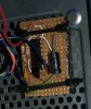
I have a tq2-l-5v which is a 5v solid state relay which if you apply voltage to pins 1 and 10, the relay closes pins 2 and 9, and leaves them in this closed state until you apply voltage in the opposite direction on pins 1 and 10 which then opens pins 2 and 9. So for this component, as soon as I get 5VDC standby voltage on the computer’s power supply I want apply voltage to pins 1 and 10. The voltage only has to be on for a moment to switch the relay because the relay will stay in its "on" state forever or until an opposite voltage is applied.

3 seconds after turning the relay on, I want to apply a voltage in the opposite direction to turn the relay off. I have a 555 timer (and 556 timers) which I think I can use to control the TQ2-L-5V relay and set the timing using an RC circuit. The issue I have is I am not sure if I can go positive to negative on pins 1-10 to start, and then negative to positive on pins 1-10 to stop; without shorting the power since I will have both positive and negative connected to both pins 1 and 10.

I found this 555 timing circuit that turns a green light on for a set time and then shuts it off and turns the red light on, (which is kind of what I what to do), but I am not sure how to convert it to get the positive to negative and negative to positive function I need on pins 1-10 on the relay.

upload_2016-4-16_12-24-56.png


I have both 555 and 556 timers, and loads of resistors and capacitors to vary the circuit timing, so I could possibly create two circuits, one to turn the relay on which only needs to apply voltage for 1 second, and a second circuit that 3 seconds after starting, will apply power in the opposite direction to turn the relay "off", but I am still worried about the shorting issue. Is it possible to prevent shorting through a creative use of diodes or possibly use a 556 timer if it can separate out the two signals going to the relay? Is it possible to do what I want with these components?

I had an earlier concept of simply applying power to a SPDT relay via a NPN transistor as soon as the 5Vdc standby power turned on, and then use an RC circuit as a time delay to eventually energize the NPN transistor after about 3 seconds to turn the relay off. I pretty sure this would work, but I am not sure that constantly applying power to the NPN transistor is a good design.

I do want this to be a onetime only switch that occurs when the power is turned on and never occurs again as long as the power is on. When I shutdown, I will do a normal shutdown of the computer and then I will turn off the main 110v power switch. The standby power actually will stay on for about 5 seconds after the 110 v power is turned off.

Thanks for any guidance you can provide.
 
Will the Advanced settings do it in BIOS i.e. Set Power up after power loss.
The other way is a momentary 1 shot using the 555 to energize a miniature relay for a fraction of a second.
Max.
 
There are no setting in a stand PC computer's Bios to turn the computer on every time that the AC power is applied. There are setting to reboot the computer when power is applied if the PC experiences an AC power loss, but those setting do not work if your shut the computer down properly and then turn the AC power off.

I could use the 555 to energize a miniature relay and that is what I was hoping to do with the TQ2-L-5V, but I was disappointed to find out that with this solid state relay I apparently have to turn the relay on and turn it off. It would have been nice if the TQ2-L-5V would simply turn itself off once I remove power from the 1-10 pins.

I have a huge surplus of electronic components since my wife's company decided to out source all their electronic repair work and they dumped all their racks of parts, but so far I have not found any small mechanical relays. I can go to the store and get one, but I was hoping that these parts are actually good for something.
 
It appears to be a latching relay, the common method for this type is to apply a voltage to latch and reverse dc voltage to unlatch, they normally stay latched even with loss of power due to the magnetic latching.
I have never checked it out, but if the momentary signal to start is just a sink to P.S. common then something like a 2n7000 may work to shunt the ON terminals triggered by the 555.
Max.
 
Just use the 5 volt powering up to charge a properly sized capacitor that feeds through a normal non latching 5 volt relay with a shunt diode in parallel with the relay coil.

As soon as the 5 volt power comes on the relay will trigger for a second or two then release and the diode will keep it from retriggering when the 5 volt power is removed and the capacitor discharges.
 
I had an earlier concept of simply applying power to a SPDT relay via a NPN transistor as soon as the 5Vdc standby power turned on, and then use an RC circuit as a time delay to eventually energize the NPN transistor after about 3 seconds to turn the relay off. I pretty sure this would work, but I am not sure that constantly applying power to the NPN transistor is a good design.
I like the simplicity of this approach for the 3 sec latching 'on' function. you can experiment with cap sizes to satisfy the coil for 3 seconds. the npn wont care how long you keep it on, just remember to protect it with a reverse blocker diode across the relay coil.
speaking of relays, to keep the 'on' and 'off' circuits isolated due to the reverse polarity requirement, i'd use dpst relays for both functions and access the 5v control wires independently for both functions to keep the reverse polarity requirements isolated
jim
 
I am confused by those 3 seconds required by the OP. In my PC, if I press the power switch for more than 1 sec I get the normal turn ON immediately followed by a turn OFF.
 
I did some more experimenting and found out that all I need to startup the computer is to ground one of the pins on the front panel header. With this information, I could use the 555 to generate a single pulse of 1 - 3 seconds duration to power a transistor if I can use the transistor to ground this pin. Now my question is "can a PNP transistor be wired so that when power is applied to it, it will connect the emitter to ground and when powered off, the emitter is not connected to anything? I may not be asking these questions correctly because the last time I had an electronics class it was called electricity and we did not have IC's and such. I do not even remember us having transistors.

The actual duration of the pulse is a minor issue and can be adjusted depending upon the RC circuit used to control the 555.
 
That is what I suggested in post #4 but you could use a small fet such as the 2N7000 to sink the pin to common (GND).
Max.
 
Max,
I saw where you recommended this approach which is why I went back and probed the motherboard to see what the front panel header pins were looking for. Since I found that I only really need to concern myself with the one pin which needs to be sinked to ground, that is why I asked about the wiring on a transistor or fet (I don't know if there is a difference). As I understand these devices, they basically act as a switch when power is applied to the base leg. My concern is that if I apply power to the base via the 555, is the collector connected to ground and therefore when power is applied, the emitter will be connected to ground? I want to be sure that I am not applying power to emitter which is connected to the header pin on the motherboard because I have no idea if that would screw up the board or not. I would rather ask what may be stupid questions instead of having to order another motherboard.
 
Looking at an ATX Motherboard main power connector there should be a single light weight green wire. thet wire is PS_ON# and on the older 20 pin connectors should be pin #14 and newer 24 pin connectors is pin #16. The downside of using this pin is the pin is normally held logic high at 5 V using the PSU 5 V StandBy. That pin must be constantly held low for the PSU to run.

Years ago I went to where the front panel momentary push button connected to the motherboard. You should find one side of the button is 5 V SB and the other side is Common (GND). I just placed a 2N2222 (or similar NPN) across the button (Collector to 5 V and Emitter to GND) and pulsed the base remotely to start the PC. Even a 100 mS pulse is adequate. You are simply placing a transistor switch in parallel with the front panel push button.

You may want to give that some thought.

Ron
 
Thanks for the information Ron. This is kind of the direction I was guided in by Max, although I was still unsure about how to exactly wire up the transistor to the motherboard. I did find the one pin on the motherboard's front panel header which when grounded would boot up the PC. I was at the point where I was looking to sink that pin to a chassis ground, but it is good to know that all I need to do is sink it to the other pin on the power switch connector.
As you can probably tell, electronics is not my forte and more often than not I end up frying something, so I wanted to be real careful this time. Since I want this to start on the application of the 110Vac power to the PC, I am going to apply the PSU 5V standby to a 555 timer circuit which will generate a single pulse of a short duration, which as you said should be sufficient to trigger the NPN transistor and boot the PC. I am glad I have finally found someone who has actually done this so I know it is possible. Unfortunately I spent 30 years working in an industry where I blew things up and still do that sometimes with this electronics stuff.

Thanks to you and everyone else who provided invaluable guidance in solving this problem for me. I will post my exact circuit when I get done so anyone else looking to do the same can find it. I know there are a lot of people, who like me are doing retrofits of older CNC mills with new PC based controls who could use this solution.
 
When I did it I either used a 2N3904 or a 2N2222 NPN transistor as a switch. When you look at the front panel push button one line will read 5 volts. This is 5 volt standby from the PSU held at 5 volts through a pull up. Placing that at a logic low momentarily is all pushing the button does. So what I did was connected my transistor collector to the 5 volt side of the switch and the emitter to the common or ground side of the switch. The base of the transistor receives the start signal through a 2.2K resistor. The resistor isn't critical and I forget what I used, may have been as low as 220 Ohms? All that was needed for remote start was a short pulse of about 100 mS. The PSU also uses pin #8 to send the motherboard a PWR_OK signal once the PSU starts and the 3.3 and 5.0 volt rails come up. Been a few years but I remember some of the stuff. Anyway you start with a common NPN switching transistor like a 2N3904 or a 2N2222. That should get you going and it gets places collector / emitter across the front panel push button as described.

Ron
 
Well I finally completed my circuit which will Boot my PC when 110 VAC power is applied to the system. Once booted, the PC runs normally and shutdown is through the normal software procedures. To repeat the "Boot on AC Power" function, the 110 VAC line has to be cycled off and then back on. The design includes a simple toggle switch to disable the Boot on AC Power function if desired. The circuit has been built and is installed in a working PC (see attached photo). Attached is the write-up on the circuit in case anyone is looking for the same functionality. It should be noted that the 5 VDC standby power stays on for about 20 seconds after the 110 VAC PC power has been shut off. This means that the automatic boot will not work until the 5 VDC drains down and goes low.
 

Attachments

  • 555_PC-Boot.pdf
    279.9 KB · Views: 303
  • PC-Boot-Circuit.JPG
    PC-Boot-Circuit.JPG
    288.2 KB · Views: 162
Last edited:
Yay, it works! :)

Ron
 
Status
Not open for further replies.

Latest threads

New Articles From Microcontroller Tips

Back
Top