Continue to Site

Welcome to our site!

Electro Tech is an online community (with over 170,000 members) who enjoy talking about and building electronic circuits, projects and gadgets. To participate you need to register. Registration is free. Click here to register now.

  • Welcome to our site! Electro Tech is an online community (with over 170,000 members) who enjoy talking about and building electronic circuits, projects and gadgets. To participate you need to register. Registration is free. Click here to register now.

Automatic Backup System Help!

Status
Not open for further replies.

Quank

New Member
Hi everybody!
I'm designing a circuit for providing power to a final load that needs 12 VDS and 600 mA aprox (ie, consuming about 7,2 W). The circuit's input is 12 VDS from a 250 W power supply that is unavailable for some hours everyday. The main function of the circuit is to switchover between this power supply when it is available and a LFP 40 AH Battery when power supply is unavailable. I've already designed the charger for charging the battery in few hours and now I'm trying to design the circuit for making the automatic switchover between main supply and battery supply to the load.
The premises are:
* When power supply is on, the power must supply directly the load and in parallel charge the battery (supply the charger)
* When power is off, the battery must supply the load and don't waste foolish energy.
* It is assumed that when power is on, can be two situations: battery is almost empty and we must spend a lot of power charging the battery while suppling the load; and battery is full and we dont must spend almost power charging, only suppling the load.
* I'm trying to get an economic circuit and not very big, because space is important
* Circuit must be reliable because it works every day
I'm trying to use MOSFETs and comparators, as the main components of the circuit, because they don't use a lot of space and they are cheap components. At the same time, they don't consume so much power knowing that It can be a lot of time in one of the two states (power on or power off).
From the next link, I found an idea for begining the automatic switchover circuit:
**broken link removed**
The circuit is attached as "4410Fig01.gif".

The first problem I have is that I want to put the charger anywhere in the circuit. Where I connect it? How I connect the battery? I need another switch?
The second problem is to find the correct MOSFETs that support a lot of current for charging the battery in few hours. At first I want to ensure 20 A!!
Thank you in advance
 

Attachments

  • 4410Fig01.gif
    4410Fig01.gif
    11.8 KB · Views: 165
The next problem that I see is that when power is off the comparator doesn't work, because everything comes from the same supply!
 
You do realise that the mosfets have an internal diode from S to D, right?

Is there any reason you don't just connect the battery across the load and the charger to the battery? You didn't mention LVD, or overvoltage protection for the battery.
 
Drawing..

Thank you dougy83 for answer!
I've been drawing the circuit for showing what I don't understand:
- "AutomaticBackupSystem_connection.png": What I want to do. The switch means that power is off for some hours and power is on for a long time (longer than power-off state).
- "AutomaticBackupSytem.png": What we are discussing. Look that I've connected the Battery Charger and the battery. At the moment I've used a simple NMOS switch. The "block" Battery Charger is detailed next.

- "BatteryCharger": It is composed with a Buck Converter and a Control Circuit. The control circuit senses the battery voltage and current and manages the Buck Converter. Here is integrated an overvoltage protection.

The problem that I see is that when power is on, battery is not charging. Is not it?
How to solve?
Thanks
 

Attachments

  • AutomaticBackupSystem_connection.png
    AutomaticBackupSystem_connection.png
    36.1 KB · Views: 151
  • AutomaticBackupSystem.png
    AutomaticBackupSystem.png
    121.1 KB · Views: 167
  • BatteryCharger.png
    BatteryCharger.png
    75.4 KB · Views: 134
Yes, I know the power mosfet has a diode inside. It is enough the diode between the charger terminals?
 
First let me start by saying that a 40 AH battery is a very large battery to be charging with a 250W PSU. Assuming your PSU supplies only 12V then you are getting about 20A of power out of it. At max charging potential you would be able to charge the battery in 2 hours, but since the load is going to demand some power as well it could take longer. You said that the load only draws 600mA from a 12V source so why do you need a 40 AH battery to power it? It's rediculously over powered and impractical unless you plan on running the load off of the battery for months at a time. Since you said that the PSU will be on for a while each day, you can use a much smaller battery that will charge more quickly and will still deliver the same amount of power needed for such a short time frame.

As for the LVD circuit, I will say that in the second schematic you have posted there are a lot of things that need to be fixed. Starting at the battery charger end of the schematic, you have bypassed the battery charger with a diode so you are forcing the battery to charge whith what ever voltage you are supplying to the circuit. This is a good way to destroy your battery or to compromise the performace of your circuit. You need to have a diod from the positve terminal of the battery to the power bus. I am also assuming that you are just using a lead acid battery to power your load, in which case you don't really need a complex circuit to charge your battery, you only need to make a trickle charger. If you are using NiCd or NiMH batteries, then your home made charger could destroy them and make them useless. If you are using any sort of lithium battery, you may want to have an emergency crew standing by for the fire that is likely to follow your first charge.

Secondly, your power MOSFET is impropperly biased, you need to swithc the source and drain pins other wise the internal power limiting diode is just bypassin your battery and the MOSFET is completely useless.

A low voltage detector is more practical on a battery powered aplication than one that usese a PSU for power. That being said, your circuit would be much more efficeint if you simply had a 12V battery that was charged with a 15V PSU and having the load connected across the battery. Then have the battery constantly powering the load, even when the PSU is connected. While the PSU is on, it will charge the battery and power the load at the same time like you want it to, but when it's removed the battery will begin powering the load without any hickup in voltage. If you try to use an LVD with a battery in that configureation, then the voltage across the load is going to drop a considerable amount untill it hits the trip point of the LVD. Instead, use the LVD to detect if the battery voltage has droped too low and have it disconnected from the circuit so that it can charge back up again once the power is applied.

Here is an example of one of my power supply designs that uses this principal:

https://www.electro-tech-online.com/attachments/radio-power-jpg.56332/
 
Thank you for answering Dragon Tamer!

First let me start by saying that a 40 AH battery is a very large battery to be charging with a 250W PSU. Assuming your PSU supplies only 12V then you are getting about 20A of power out of it. At max charging potential you would be able to charge the battery in 2 hours, but since the load is going to demand some power as well it could take longer. You said that the load only draws 600mA from a 12V source so why do you need a 40 AH battery to power it? It's rediculously over powered and impractical unless you plan on running the load off of the battery for months at a time. Since you said that the PSU will be on for a while each day, you can use a much smaller battery that will charge more quickly and will still deliver the same amount of power needed for such a short time frame.

I know that at first the system seems poorly designed, but I have not specified all the detailed assumptions:
* The load is at least 7.2 W, but I'm sure that will higher at the end of the design
* The load needs to be supported 24 h / 365 days. In some cases, power is going to be available only 6 hours every day!! It means that during this 6 hours time system must charge the battery for the rest 18 h battery suported (24-6 = 18).
* The complete system: PSU+Battery+Circuit+Load, etc.. Has a very strict space limitation. This means that the choice of the battery has been done to find the best space-capacity-battery security (and price).
* Battery technolgy is LFP and the charger has a chip for making the charging with enough security. Space restriction forces us to use a 4.2 V battery!!
* The system must be oversized, just in case

As for the LVD circuit, I will say

Let's priorize for the moment the charger system and the powering of the load. The second priority is a LVD circuit. So, let's forget the LVD for the moment.

that in the second schematic you have posted there are a lot of things that need to be fixed. Starting at the battery charger end of the schematic, you have bypassed the battery charger with a diode so you are forcing the battery to charge whith what ever voltage you are supplying to the circuit. This is a good way to destroy your battery or to compromise the performace of your circuit. You need to have a diod from the positve terminal of the battery to the power bus.

Thank you. I will correct. I can't attach correction now.
This last diode is for avoiding the discharging of the battery into the PSU?

I am also assuming that you are just using a lead acid battery to power your load, in which case you don't really need a complex circuit to charge your battery, you only need to make a trickle charger. If you are using NiCd or NiMH batteries, then your home made charger could destroy them and make them useless. If you are using any sort of lithium battery, you may want to have an emergency crew standing by for the fire that is likely to follow your first charge.

Battery technolgy is LFP and the charger has a chip for making the charging with enough security. Space restriction forces us to use a 4.2 V battery!!

Secondly, your power MOSFET is impropperly biased, you need to swithc the source and drain pins other wise the internal power limiting diode is just bypassin your battery and the MOSFET is completely useless.

Thank you. I will correct it.
Is going the MOSFET to turn on with a good Rdson (little loses)? It must be for hours.. It is going to get a good Vgs? Can you explain me?

A low voltage detector is more practical on a battery powered aplication than one that usese a PSU for power. That being said, your circuit would be much more efficeint if you simply had a 12V battery that was charged with a 15V PSU and having the load connected across the battery. Then have the battery constantly powering the load, even when the PSU is connected. While the PSU is on, it will charge the battery and power the load at the same time like you want it to, but when it's removed the battery will begin powering the load without any hickup in voltage. If you try to use an LVD with a battery in that configureation, then the voltage across the load is going to drop a considerable amount untill it hits the trip point of the LVD. Instead, use the LVD to detect if the battery voltage has droped too low and have it disconnected from the circuit so that it can charge back up again once the power is applied.

Here is an example of one of my power supply designs that uses this principal:

https://www.electro-tech-online.com/attachments/radio-power-jpg.56332/

Let's forget the LVD for the moment. As I've explained, space restriction forces a 4.2 V, so I suppose that I can't connect the battery directly to the load and power bus (12 V). This is a good mistake I haven't put in my circuit (I will correct). I must include a boost converter.
In this situation, don't you think is a good idea to put a switch between the battery and the load? Another voltage comparator?
I'm sorry, the circuit that you attached is too complex for me. Can you give me some keys?
 
The only instance I can think of that would have a load drawing a specific wattage would be a light bulb of some kind, or a heater. In both cases the wattage demand of the load will decrease as the voltage decreases unless there is a circuit in place to modify the current going through the load. It would help if we could get some more info about the load attached to the power supply. The only thing I can think of that would run with both 12V and 4.2V is maybe digital logic if there was a voltage regulator in line. Other wise the lower voltage would cause the circuit to behave in very strange ways or not even work at all. Just because the load's specificatons at 12V are 600mA and 7.2W doesn't mean that they are the same at 4.2V. It is much more likely that the load will draw 2.52W at 4.2V if the current is fixed. Other wise the current draw will increase from 600mA to 1.7A if the power is fixed. Keeping this in mind your battery is a 40AH battery so it will deliver power for 40/1.7= 23.5 hours or 40/0.6= 66 hours. So your battery is more than large enough.

You are using Lithium batteries in your supply, this is a good choice because of the power they deliver for their size and weight, but be carefull not to charge or discharge them too quickly because the can catch fire or explode. If the do, you won't be able to put it out. Burning lithium has it's own oxidizer so it can burn just about anywhere. The good thing about your lithium batteries is that they have plenty of power to give to your load.

You only need the diode that is bypassing the battery charger if you have components in the PSU that are sensitve to voltages when they are turned off. It's probably a good idea to include the diode anyway.

When you are trying to switch the voltage from the PSU to the battery you have to consider the two possible devices you can use in your circuit, a power transistor or a power MOSFET. The choice will depend on what is more importatnt to your load, voltage or current. If current is more important then you will want to use the power tranisistor since it does not have a fixed current drop across it but it does have a fixed voltage drop. Depending on where you have the transistor located it can be either a 0.7V drop or a 1.4V drop. If voltage is more important to your load then MOSFET's are the way to go. The don't have a fixed voltage drop but they do have an internal resistance that will handicap your load at higher currents. This can be worked around by connecting several MOSFETs in parallel so that only a fraction of the total circuit current is going through them. It is exactly the same as putting resistors in parallel to reduce the voltage drop and increase current. If you are simply using a diode, then there is no real need to have any sort of a sensor control the source of power. As soon as the PSU voltage drops below 3.5V the battery will kick in and start driving the load (4.2-0.7=3.5V).

If your load needs a specific voltage or current you can make better use of the batteries by taking advantage of a buck/ boost system. If you connect all of the batteries in parallel then you can boost their voltage from 4.2V to 12V using a boost converter if you are willing to sacrafice some current (pretty much irrelivent right not). If you connect all of the batteries in series you can get an output of 12V or 4.2V and get more current from the conversion. Buck and boost converters have about a 95% efficiency in their conversion so they waste very little power. A voltage regulator on the other hand will waste anywhere from 1W to 30W depending on the conditions.

I would not put a switch between the battery and the load especialy if it needs to switch over very quickly. As I said just having a diod there will allow the battery to kick in and continue powering the load once the PSU has been turned off. If you do, you don't need a voltage comparator to activate the battery, it will activate itself.

The circuit that I attached is a power supply that I am working on for my radio. I have the load connected directly to the battery (not bypassing the sense resistor for the battery charger). The relay that is shown imidiately after the battery is a bypass relay. As long as the unit is pluged into the wall, the bypass relay is engaged and will allow current to flow around the switch that is in series with the load. The switch is there so that I can turn the unit off when it is running off of the battery to make it last longer. The MOSFET that is connected to the negative terminal of the load is there to ensure that the battery has adequet protection from excessive discharge. If the voltage drops below 9V it warns that the voltage is getting low, if it drops below 8V it disconnects the battery from the load so that it can be recharged once power is reapplied. If the voltage drops below 1V per cell then the battery charger will not recharge the batteries. As long as there is AC power applied, the sensor will allow the load to be powered all the time. The microcontroller is simply there to make sure that everything is opperating properly. As soon as something goes wrong, it sends a signal to the rest of the radio about what has just gone wrong and the a request on how to fix it. The radio will respond appropriatley.

Regarding your orrigonal post, a MOSFET that is capable of handeling 20A is the one that I used in my schematic. The IRL3103 can handel 63A and voltages up to 32V. Just make sure you have an appropriate heat sing connected to it.
 
Last edited:
I've been rethinking the circuit and have made ​​some improvements, before answering.
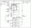
I attach the new circuit "AutomaticBackupSystem_v2.png".
I think the new circuit will do exactly what I want:
- WHEN POWER IS ON: Connect the PSU to the load, connect the charger to the battery. Not connect the battery to the load.
- WHEN POWER IS OFF: Connect the battery to the load with a boost converter for supplying 12 V at the load.

The only instance I can think of that would have a load drawing a specific wattage would be a light bulb of some kind, or a heater. In both cases the wattage demand of the load will decrease as the voltage decreases unless there is a circuit in place to modify the current going through the load. It would help if we could get some more info about the load attached to the power supply. The only thing I can think of that would run with both 12V and 4.2V is maybe digital logic if there was a voltage regulator in line. Other wise the lower voltage would cause the circuit to behave in very strange ways or not even work at all. Just because the load's specificatons at 12V are 600mA and 7.2W doesn't mean that they are the same at 4.2V. It is much more likely that the load will draw 2.52W at 4.2V if the current is fixed. Other wise the current draw will increase from 600mA to 1.7A if the power is fixed. Keeping this in mind your battery is a 40AH battery so it will deliver power for 40/1.7= 23.5 hours or 40/0.6= 66 hours. So your battery is more than large enough.

The load is a kind of router that works with a fixed voltage of 12 V. This means that we must ensure 12 V at the output! I attached in this post the new version of the circuit with a "block" called Boost Converter. This block will transform the 4.2 V battery output to 12 V fixed. The load current varies depending on router consumption (its activity, people connected, etc..). Let's assume that the maximum current is 1 A.

You are using Lithium batteries in your supply, this is a good choice because of the power they deliver for their size and weight, but be carefull not to charge or discharge them too quickly because the can catch fire or explode. If the do, you won't be able to put it out. Burning lithium has it's own oxidizer so it can burn just about anywhere. The good thing about your lithium batteries is that they have plenty of power to give to your load.

Thank you. I will be carefull.
Due to space constraints, I can only put a single 4.2 V battery, which necessarily need a boost converter (or similar voltage regulation) to provide 12 V to the load.

You only need the diode that is bypassing the battery charger if you have components in the PSU that are sensitve to voltages when they are turned off. It's probably a good idea to include the diode anyway.

As you can see in the attached file "AutomaticBackupSystem_v2.png", I put a diode before the bifurcation of the charger / battery, to prevent reverse power from the battery. I think this is no longer necessary. Is that correct?

When you are trying to switch the voltage from the PSU to the battery you have to consider the two possible devices you can use in your circuit, a power transistor or a power MOSFET. The choice will depend on what is more importatnt to your load, voltage or current. If current is more important then you will want to use the power tranisistor since it does not have a fixed current drop across it but it does have a fixed voltage drop. Depending on where you have the transistor located it can be either a 0.7V drop or a 1.4V drop. If voltage is more important to your load then MOSFET's are the way to go. The don't have a fixed voltage drop but they do have an internal resistance that will handicap your load at higher currents. This can be worked around by connecting several MOSFETs in parallel so that only a fraction of the total circuit current is going through them. It is exactly the same as putting resistors in parallel to reduce the voltage drop and increase current. If you are simply using a diode, then there is no real need to have any sort of a sensor control the source of power. As soon as the PSU voltage drops below 3.5V the battery will kick in and start driving the load (4.2-0.7=3.5V).

I will use a MOSFET because load is VOLTAGE FIXED. On the other hand, I think is more interesting to use a comparator and a MOSFET (instead of a simple diode) because I can improve the circuit by changing the minimum voltage threshold to activate the battery. Also interesting is the effect "hysteresis" of the comparator, which the diode does not provide.

If your load needs a specific voltage or current you can make better use of the batteries by taking advantage of a buck/ boost system. If you connect all of the batteries in parallel then you can boost their voltage from 4.2V to 12V using a boost converter if you are willing to sacrafice some current (pretty much irrelivent right not). If you connect all of the batteries in series you can get an output of 12V or 4.2V and get more current from the conversion. Buck and boost converters have about a 95% efficiency in their conversion so they waste very little power. A voltage regulator on the other hand will waste anywhere from 1W to 30W depending on the conditions.

I will try to use a boost converter because is much more efficient. Do you recomend any one? I'm looking to supply 1 A and to convert 4.2 to 12 V. Better to integrate the MOSFET and the clock inside the chip. Better to be a Through Hole chip..

I would not put a switch between the battery and the load especialy if it needs to switch over very quickly. As I said just having a diod there will allow the battery to kick in and continue powering the load once the PSU has been turned off. If you do, you don't need a voltage comparator to activate the battery, it will activate itself.

The last circuit was bad designed. I need a switch to connect the battery to the load, not to desconnect the battery from the charger!


The circuit that I attached is a power supply that I am working on for my radio. I have the load connected directly to the battery (not bypassing the sense resistor for the battery charger). The relay that is shown imidiately after the battery is a bypass relay. As long as the unit is pluged into the wall, the bypass relay is engaged and will allow current to flow around the switch that is in series with the load. The switch is there so that I can turn the unit off when it is running off of the battery to make it last longer. The MOSFET that is connected to the negative terminal of the load is there to ensure that the battery has adequet protection from excessive discharge. If the voltage drops below 9V it warns that the voltage is getting low, if it drops below 8V it disconnects the battery from the load so that it can be recharged once power is reapplied. If the voltage drops below 1V per cell then the battery charger will not recharge the batteries. As long as there is AC power applied, the sensor will allow the load to be powered all the time. The microcontroller is simply there to make sure that everything is opperating properly. As soon as something goes wrong, it sends a signal to the rest of the radio about what has just gone wrong and the a request on how to fix it. The radio will respond appropriatley.

I've been studying a little bit your circuit. I understand that ICL7665 do almost all the work regarding the LVD. Doesn't it? Why not to use a MOSFETs replacing the relay? I guess you do not have many space constraints... Relay is wasting energy when power is on, isn't it? Very advanced circuit...
Which program do you use to draw the schematics?

Regarding your orrigonal post, a MOSFET that is capable of handeling 20A is the one that I used in my schematic. The IRL3103 can handel 63A and voltages up to 32V. Just make sure you have an appropriate heat sing connected to it.

Thank you very much! It is a good MOSFET.
Can I use correctly an NMOS in the new position (between the battery and the boost)? I am trying to get a good switch, but here is not necessary so much current so I think is a little oversized to put two NMOS (for losses and for saving the heatsinks). I want the circuit not too large. I have space constraints.
 

Attachments

  • AutomaticBackupSystem_v2.png
    AutomaticBackupSystem_v2.png
    127.6 KB · Views: 168
The ~5V output from the comparator won't be high enough to turn the MOSFETs on, or fully on, if their source voltage is ~ 4V. So you will need a comparator positive supply >>5V.
 
Sorry I didn't respond to your post sooner, I wasn't feeling well and had to go lay down.

You are sort of handicapping me with the block diagrams. You are forcing me to make assumptions about your circuit so my information does leave some room to be improved. You mentioned a lithium charger IC, I would very much like to examine that so I can give you the best advice on how to integrate it.

I am still convinced that the easiest way to have the circuit switch over is using diodes. It is simple, reliable and is very unlikely that it will break. You should still have a diode on the output of the boost converter to protect the booster IC from excessive voltage.

You mentioned that you wanted to have a comparator switch over when the PSU voltage drops too low. While I admire your ambition, in order for something like that to work you need to have a decently higher output voltage from the PSU so that there is room for the voltage to drop before the battery kicks in to power the load. Right now it is going to be extremely hard to measure the voltage drop because you are trying to sense a voltage slope of less than 0.5V. Your sense resistors would need to be a ridiculously low tolerance. A value of 0.1% may not even be enough.

You can easily have the boost converter kick in using a comparator since most converters usually have a shut down pin connected to them for external logic to control them. The exact converter you use is up to you. There are a lot of ICs that can boost your voltage to 12V. The current of the output usually depends on the inductor used in the circuit.

A good cheap comparator to use is an LM393, it is a dual comparator but it will work safely up to 30V DC and can easily be programed for your function.

Concerning my power supply, no space is not an issue but the relay that I used is fairly small, it's only a few centimeters of space that it occupies. I chose a relay because it is simple and it will do it's job until it wears out. Since my power supply is rarely intended to be unplugged from the wall it will not experience very many cycles so it should last for a long time even though it is nearly 15 years old.
 
Dragon Tamer, don't worry, I hope you feel better...
I gonna use the LM393. I like it.
Now we have 2 options:
1- Look for a Boost Converter IC that have a "shut down" pin. This will "disconnect" completely the battery (4.2 V) to the 12 V supply? I'm interested in using ICs that are commonly available, because I don't want an IC that is going to become obsolete or "the only solution" in a few years..
2- Use the MOSFET transistors for "disconnecting" tha battery to the boost.
Which do you prefer?

And here comes the million dollar question: When power supply is off, what happens to the comparator that is fed from it? It is going to turn on the connection from the battery to the boost? What can I do?
Thank you!
 
When the power supply is removed, the comparator is going to shut down. If you connect the comparator to the same leads that power your load then it will always receive power from either the battery or the PSU. The LM393 has a fairly low current draw, at 5V it draws about 400uA-1mA at 30V it draws about 1mA-2.5mA. It should not affect your circuit very much.

The boost converter may provide some isolation between the battery and the 12V rail but it depends on the converter you use. Some circuits have a diode that is built in to protect the circuit from reverse voltage. Some don't, with this in mind you must consider this when you choose your boost converter. Based on how you want to build the circuit, the battery must be completely isolated from the 12V rail while it is charging.

I would personaly prefeer to have the boost converter shut down with the comparator rather than have MOSFETs switch over. It is a simpler solution and will give your circuit a little bit more efficiency.
 
Thanks Dragon Tamer,
I will follow your recommendations. Good advice.
I gonna implement the inprovements to the circuit.
 
Status
Not open for further replies.

Latest threads

New Articles From Microcontroller Tips

Back
Top