Continue to Site

Welcome to our site!

Electro Tech is an online community (with over 170,000 members) who enjoy talking about and building electronic circuits, projects and gadgets. To participate you need to register. Registration is free. Click here to register now.

  • Welcome to our site! Electro Tech is an online community (with over 170,000 members) who enjoy talking about and building electronic circuits, projects and gadgets. To participate you need to register. Registration is free. Click here to register now.

Auto Satellite Dish Repairs .. .. .. maybe .. .

Status
Not open for further replies.

Musicmanager

Well-Known Member
Hi Guys

I'm hoping to find someone familiar with this equipment and offering advice .. ..

I'm after one of these .. ..
s-l1604.jpg


It's an automatic satellite dish suitable for fixing to the roof of the new caravan I've just bought. As a new item, by the time you've bought the unit and the various bits and pieces that go with it you've handed over £650 to £800 .. .. ..

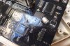
However, there is one on fleabay .. spares or repair .. .. quote '' a capacitor has come off the main board .. .. .. "

s-l1600.jpg


Novice I am, naive I am, but on face value that doesn't look like too difficult a fix to me .. .. ..

Is it likely there is 'knock on' damage elsewhere on the board ? Am I missing something ?

I'd appreciate any thoughts .. .. .. .

S

 
SMD aluminum electrolytic capacitors and TH caps are not that different in size. So replacing it per se is not that hard, even if the pads are damaged. A fiberglass "rubbing brush" can create new areas easily through the soldermask to solder the device to. What you don't know is whether there is any inner damage (if more than 2-layer board) and whether that is the only damage.

As for "knock on damage" , I suspect you would need a better picture to see possibly buried traces as with a board of more than 2 layers. Of course, the soldermask is black, so that is not easy to see, and an eBay seller is not going to send you an X-ray.

If it is just a 2-layer board and the price is right, I would not be that reluctant.

John
 
Looks to me as though the 44-pin chip at the bottom of the pic has a nasty bulge in its top surface?
 
Mmm ... .. been eating the carrots in Cardiff !? I hadn't noticed that .. .. Well Done .. TY

S
 
Didn't notice that either. It could also be an overly thick area of conformal coating that was just about to run. Does the dealer have any more views of the board? What is the chip (if you can read it) or can seller give that information? It does not look like a difficult chip to replace, if it is not something that has to be programmed. Of course, if that chip is bad, the price would really go down in my opinion, as the risk is a lot higher.

John
 
Don't think it's the conformal coating, since the apparent bulge extends partly underneath fairly legible text.
 
There's a shadow extending from ~pin 5 to pin 11, IMO caused by a 'hill' to the left.
 
I've asked the seller for some decent pics of the whole board and especially that chip .. ..

S
 
Hi MM , Good reception at top of Porlock Hill for testing... :)

Looks like a shadow of the camera...
 
Well, I'll wait and see if some more pictures arrive and some better detail ... .. .. .

.. .. .. . what concerns me some is how that cap came off the board in the first place. I don't believe it would just fall off, tearing up some track with it so something encouraged it - either a physical blow or an electronic one.

I've done a bit of research into the serial number and the date code and I think the unit is quite old, so maybe I'm on a sticky wicket, Ooops! sorry if there are any SA's listening ! :)

GD... What are you doing up there ??

Thanks for your thoughts Guys

S
 
Believe it or not, one of my thoughts was that that capacitor was ripped off the board intentionally to divert attention from the real problem. After all, it does look kind of staged. Let's see how the seller responds.

Call me paranoid?

John
 
.. .. ... and just to confirm all our suspicions, the seller has just declined to provide anymore pictures .. .. .. completely ignored my questions about the 'blown' chip .. ..and suggested he may be able to sell it to someone else ! They're two a minute, over here !

A narrow escape !

Thanks for keeping me on a even keel Guys, much appreciated !!

Paranoid ? You can call me what you like, but don't call me late for my dinner ! :D

Bestest .. .. .. .

S
 
Go have a sip+ (i.e., 2 oz) of Lagavulin 16. I know Ian would approve of that. Count yourself lucky.

John
 
There is a film of coating on the board, glossy by the looks of it. Also whatever knocked that cap loose would have either been some serious impact or done during any assembly. Odds are the board has been roughed a bit.
 

Attachments

  • Sharp light adjust.jpg
    Sharp light adjust.jpg
    62.2 KB · Views: 265
Go have a sip+ (i.e., 2 oz) of Lagavulin 16. I know Ian would approve of that. Count yourself lucky.
Even better... Send me some...!!
For what its worth, that also looked a bit hooky for me...
 
Morning Folks

Following your advice, I did show this guy a clean set of heels albeit a little slow moving and I subsequently purchased a Megasat Automatic Dome which has been installed on my van and works extremely well, a great bit of kit.

However, during my search for this equipment a friend gave me a CAMOS PAPSA Basic along with a statement that it had never worked for him and therefore must
be faulty.

PAPSAmg_features.jpg


After a bit of a play I have concluded that the problem is a missing component - a Power Inserter - based on the notion that if I take the cover off the dish body and apply 12vdc to the power terminal on the circuit board the whole thing leaps into life.

Contact with CAMOS confirmed that they don't market PAPSA anymore and that they are made by SATMARK who are in S. Korea. Unfortunately, I cannot get SATMARK to respond to any communication ( they're probably too busy ducking the IFO's )

There are a number of similar looking components including a variety of voltages available, especially on Ebay, and they all imply by means of a sketch that the power is fed to the antenna but blocked from the receiver. My confusion is how this is done, because the receiver in operation would require two way communication with the dish.

Does anybody have any experience laden advice to offer please ?

Thanks
S
 
My guess would be that the power inserter would just be an RF choke in series with the DC feed to the centre conductor of the coax. The signal from the LNB is in the 1000 to 1300 MHZ range (From memory.) The wiring between the coax connectors would need to be very short at this frequency. Ideally a stripline on a PCB with 75 ohm characteristic impedence. The RF choke would only need to be a few turns of wire. The DC input connection would be better going through a feedthrough capacitor of about 1 nF. I did think of suggesting a masthead amplifier power inserter but you would need to modify one of these by shorting out the capacitor that blocks the DC to the connector that goes to the TV. I am assuming that the settop box in your setup is also powered via the coax. If the settop box is not powered via the coax then this capacitor would be needed. By doing a search for "Masthead amplifier power inserter" I found some on this Amazon page. The third item (Axing TZU 15-02 Remote Power Inserter) looks like it may be what you need. It looks like you would also need a back to back F type socket to connect the coax to the side that goes to the antenna unit.

Les.
 
Status
Not open for further replies.

Latest threads

New Articles From Microcontroller Tips

Back
Top