Continue to Site

Welcome to our site!

Electro Tech is an online community (with over 170,000 members) who enjoy talking about and building electronic circuits, projects and gadgets. To participate you need to register. Registration is free. Click here to register now.

  • Welcome to our site! Electro Tech is an online community (with over 170,000 members) who enjoy talking about and building electronic circuits, projects and gadgets. To participate you need to register. Registration is free. Click here to register now.

Audio Questions

Status
Not open for further replies.

srobertjames

New Member
Hi all. I have a few audio questions:

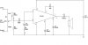
1. My circuits are powered by +5V. The op apms require a 2.5V reference. I'm using 2 resistors. Is there a better way to do this?

Are there voltage regulators which will give a +5V out and at the same time a +2.5V out? Should I just use 2 independent regulators?

I think Maxim has some ICs which may do this, but they're all SMD, and I'm limited to breadboarding = DIPs.

2. I need a Butterworth filter. But the values I come up with are no where near the standard vals available. Are there charts for filters which will give me standard component values?

3. What's the simplest way to make a triangle or saw wave? I use capacitors, but, they're not perfectly linear. Is there a better way which is still simple?

Thanks.
 
Hi all. I have a few audio questions:
I need a Butterworth filter. But the values I come up with are no where near the standard vals available. Are there charts for filters which will give me standard component values?
Filters use resistors and capacitors. 5% resistor values are available so use them with a few capacitor values.

What's the simplest way to make a triangle or saw wave? I use capacitors, but, they're not perfectly linear. Is there a better way which is still simple?.
A capacitor as the integrator feedback for an opamp makes a perfectly linear triangle or sawtooth wave, if the opamp is half-decent (don't use a low frequency LM358, LM324 or 741 opamp).
 
Filters use resistors and capacitors. 5% resistor values are available so use them with a few capacitor values.

Okay. But my Butterworth chart shows capacitor values with several significant digits. I have caps in the 10x, 22x, and 47x range - nothing like 1.032 or any multiple of ratios.
 
Okay. But my Butterworth chart shows capacitor values with several significant digits. I have caps in the 10x, 22x, and 47x range - nothing like 1.032 or any multiple of ratios.
You pick the closest 5% cap value and the closest 1% resistor value.
 
2. I need a Butterworth filter. But the values I come up with are no where near the standard vals available. Are there charts for filters which will give me standard component values?
Try the free FilterPro from TI. It has a setting for standard values.
 
Most lowpass and highpass filters have gradual slopes so the cutoff frequency does not need extreme accuracy. 5% resistors and capacitors usually work fine for me.

I used Butterworth switched-capacitor lowpass filter and notch filter ICs with a slope of up to 8 orders and they had high accuracy built-in.
 
If you are looking for a fairly effective audio amplifier, then I would recommend this circuit:
**broken link removed**

the only difference in the circuit I used is; C2 is 10uF, C3 is 100uF, C4 is 1nF :)
I did have a problem with my circuit (as some may know my iPod was fried from a previous experiment) but I threw in a 1k pot to balance the difference from my iPod, But my problem is that the sound is crackling, (i think the voltage is spiking, but without an oscilloscope I can't tell) :( could someone give me a quick tip?
 
If you are looking for a fairly effective audio amplifier, then I would recommend this circuit.
The Japanese BA546 amplifier IC has the same low output power as the LM386 amplifier IC (0.2W at clipping into 8 ohms with a 6V supply) except its distortion is much higher.
 
The difference of what?

the difference of my iPod's output, remember the left headphone is slightly louder due to my egarness and impatience (in other words it was fried).

You forgot to post what the 1k pot is connected to.

the 1k pot is connected to the input by pin 2, pin 1 and 3 are connected to the inputs

Why don't you post the entire schematic?

...it's kind of embarrassing, but i haven't figured out how...:(...OHHH!!! THAT'S WHAT MANAGE ATTACHMENTS MEANS!!!
 
This is the circuit the way I built it:
 

Attachments

  • ba546.JPG
    ba546.JPG
    29.4 KB · Views: 189
  • resistance-is-futile.jpg
    resistance-is-futile.jpg
    13.3 KB · Views: 172
Status
Not open for further replies.

Latest threads

New Articles From Microcontroller Tips

Back
Top