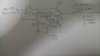
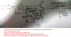
Design an audio amplifier that can deliver an average power of 280mW to a 64 ohm speaker.
Signal which is used to amplify is 2000Hz sinewave with a peak-to-peak amplitude 0.9V.
provided with LM741 op-amp, resistors, capacitors, inductors and 2N2222 transistors.
I need guidance to design a circuit .
Signal which is used to amplify is 2000Hz sinewave with a peak-to-peak amplitude 0.9V.
provided with LM741 op-amp, resistors, capacitors, inductors and 2N2222 transistors.
I need guidance to design a circuit .
Last edited: