Boy do I wish I'd gone searching for an electronics forum for help on this first.
Anyway, I've found these instructions in several places but they are missing all the key schematics and pictures!!!!!
I went and got all the parts in the list but when I went to start putting it together I realized I was lost.
I also got a little 555 timer kit that can pulse .5 - 5 seconds and pause 2-60 seconds. I was hoping the kit would help me figure out how to hook everything else up but it really doesn't.
I guess what I mainly need to know is what other connections on chips 2 and 3 need to be made other than the time. Also, what does the 4th chip do?
The parts I actually have (since I could not find the specific # of some)
Relay 2- 9vdc (3A 250V~, 3A 30V-) (I do have a few others lying about also)
DC power supply 9vdc 200mA (I also have some variable and 12v DC power supplies to work with)
I'll just wire up a power cable rather than a power strip (wiring and connectors I'm good with, I just need the help with circuit layout/design)
Small bread board and wires to go with it.
Chip 1 (got 2) NE555 general purpose single bipolar timer
Chip 2 (got 4) MC74HC402 14 stage binary ripple counter (Motorola)
Chip 3 (same as chip 2, only got 4 of those chips total)
Chip 4 (got 2) MC74F74N Dual D-Type Flip-Flop (Motorola)
Capacitors (got 2) minature 3-30 pf adjustable capacitor
Resistors (got 4) 200 K ohm Bourns 3299 vertical trimming potentiometer
_____________________________________________________________
Here are the additional parts I have from the little timer kit I got
I've already built this on the bread board and got it to work so I'm feeling a little better about my electronics abilities (been a while since college electronics classes.)
circuit board
3 1k ohm resistors
2 1N4148 Diodes
1 1N4007 Diode
1 1M ohm trimpotentiometer
1 50 k ohm trimpotentiometer
1 100nF (104, u1) Capacitor
2 100uF capacitors
1 3mm LED
1 IC socket for the 555 chip
1 555 chip
1 dual screw terminal for board power
1 three way screw terminal for relay controlled device
1 12vdc relay (15 A at 125 VAC, 10A at 28-240VDC)
***********************************************
What I'm trying to do with this is trigger a 12 volt solenoid actually. Probably only need a few seconds on and then 10-20 minutes off.
************************************************
However, I have plenty of other ideas if this works. I'll probably be back asking how to make some sort of timer that can reverse polarity on the pulse so I can use it to trigger a door lock actuator.

Anyway, I hope this wasn't too long for a first post.
Thanks in advance for any help!
Anyway, I've found these instructions in several places but they are missing all the key schematics and pictures!!!!!
Parts List:
One solid-state relay (you choose the amperage to suit, I used 10 Amp / 120V, US$6.50 used).
A DC power supply (anything from 5 to 9V DC is fine, I used one from an old
"DiskMan").
One power-strip.
One "Bread Board" (We will build our little circuit on this, US $3 or less).
Four chips, some jumper wires of various lengths, one capacitor, and two
resistors. (See picture for specifics about US $3 or less).
Two wires approx 1’ (use some cord from the DC power supply mentioned above).
This is going to be so easy, you won't believe it; they charge US$90 for these in many Grow shops!
Note that EXACT product codes are not important in selecting circuit parts. But, what IS important is for the numeric part of the code to match mine and for the number of pins to be the same. For example, if you found a 16PIN "TC4013BP" that would be fine even though the one I have says "TC4013BF". The capacitor can be any type, but if you get a polar one
like I did, make sure it goes in the proper direction. The resistors don't
matter so much, just get the res values correct.
Setting up the breadboard
The Breadboard has two sides, which are electrically insulated from each other.We will call the left side GROUND and the right side POWER. We supply power and ground to the board by plugging our DC Power supply leads into bottom of the board (as shown). I recommend soldering these connections to pieces of (more rigid) jumper wire. You must match the positive wire from the power supply to the positive (right) side of the breadboard, and the negative lead to the left side. Usually, the positive wire will look different (e.g. have a white stripe like mine). The outermost holes on each side of the board are used to distribute power and ground (respectively) to an entire row of the board (I have wired the
first row to both power and ground sides in the photo below to illustrate this).
The chips have either 8 or 16 pins each. The pins are numbered counter-clockwise (from bottom left of chip) as shown.
Building
You may connect the power and ground connections from the DC power supply anytime but DON’T PLUG IN BOARD DURING ASSEMBLY!
Note: When putting on the chips exact row positions don’t really
matter, just as long as the chips go in the order specified and are "down
the middle" of board, with lettering READABLE FROM THE GROUND SIDE.
Install all the chips [refer to previous picture]:
Chip#1 is the 555 timer chip.
Chip#2 = 4020B counter chip.
Chip#3 = another 4020B chip.
Chip#4 = 4013BF dual D-type Flip Flop.
Note: We will only use one side of the "dual" F.F. I used a dual because it was available (and commonly found).
Wiring bottom chips
Note how pin8 on Chip#3 got its ground connection from a different row. You can get Power or Ground connections (respectively) from anywhere on the outer pin columns.
Note the optional LED's. The green taps into pin1 on chip#4. This LED will show when the timer is ON (helps check things). The Green LED's other leg plugs into the Ground (as shown). The Red LED will indicate when the timer is in the OFF state. It taps pin2 of Chip#4, and also needs to be grounded (as shown). NOTE: Make sure the LED's you use have built in resistors, or else add a little resistance in series with each LED.
The Relay
Now that the logic portion of the timer is done. Go ahead and plug the DC Power supply block into the wall. The green and red LED's should alternate 2 seconds green, 2 seconds red. This is the troubleshooting setting (we will adjust ON/OFF times later).
Connecting the relay:
The Solid State relay has two ends, the DC control end, and the AC power end. ***Caution*** AC current can kill you, so please be careful. Make sure the power strip is UNPLUGGED.
We begin by slicing through the outer plastic of the Power Strip's insulation, about a foot or so from the plug. Peel back the insulation to reveal three wires (white, green, and black). The black one is the POWER wire, the one we will splice into the AC side of the relay. Cut the black wire and cut and peel back some insulation from each cut end. Make a small loop on each cut end, and screw down these loops under the relay's screws (AC end). [See picture for details]
Connect two small (8-12") pieces of wire [see parts list] to the Relay's DC
power and ground screws. Tape up the entire relay (especially the AC end) with black electrical tape (or duct tape). This will prevent any contact shorts and improve safety.
Plug in the Negative (black) and Positive (red) wires from the relay to where the GREEN LED was before (as shown). Note that I have soldered the ends of these wires to pieces of jumper wires (again, for more rigid connections).
Note that I have replaced two key wires from previous pictures with the YELLOW and GREEN wires (for clarity). Leave these wires connected at chip #4.
To Set ON/OFF times:
Chip #3 controls OFF time.
Chip #2 controls ON time.
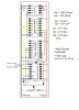
To change these times, simply plug the Yellow or Green wires into other pins (on Chips 2 and 3) as follows:
The following times are valid for chip 2 (ON time) and chip 3 (OFF time):
Pin # Schematic Pin Delay Time
9 Q1 2 sec
7 Q4 16 sec
5 Q5 32 sec
4 Q6 ~ 1 min
6 Q7 ~2 min
13 Q8 ~ 4 min
12 Q9 ~ 8 min
14 Q10 ~ 17 min
15 Q11 ~34 min
1 Q12 ~ 68 min
2 Q13 ~ 2 hr 15 min
3 Q14 ~4 hr 30 min
***Remember that the pins are numbered from 1-16 and arranged counter clockwise from bottom left of chip. Do not plug into any other pins besides those listed in table above!***
Sample time setting:
To set 64 sec. ON / 256 sec. OFF, plug the Yellow wire at chip #2 into pin#4, plug the Green wire at chip #3 into pin#13.
The board and relay could be fastened inside of a small plastic case with holes cut for the power strip cord ends. Make sure to keep components from touching though. Simply plug in your appliance into a spot on the power strip, plug in the strip and DC power supply, and set the ON/OFF times.
Here's the schematic of the completed cyclestat.
Be sure to add a filter capacitor as the schematic indicates (not shown in photos) to ensure proper timer functioning.
TIMER IMPROVEMENT
Below is the updated timer layout, featuring an "automatic on" function that restarts the timer in the ON position when power is applied. The resistance/capacitance values on the RC circuit are subject to what works. (The stated values worked for me, It's all about resetting the chips for long enough time intervals when power up occurs -- play around to find what works best for your timer.)
Shown Values:
Res. at bottom (added RC circuit) = 1K ohm
Res at middle = 10K ohm
Cap. at bottom (RC circuit) 68 uF.
I went and got all the parts in the list but when I went to start putting it together I realized I was lost.
I also got a little 555 timer kit that can pulse .5 - 5 seconds and pause 2-60 seconds. I was hoping the kit would help me figure out how to hook everything else up but it really doesn't.
I guess what I mainly need to know is what other connections on chips 2 and 3 need to be made other than the time. Also, what does the 4th chip do?
The parts I actually have (since I could not find the specific # of some)
Relay 2- 9vdc (3A 250V~, 3A 30V-) (I do have a few others lying about also)
DC power supply 9vdc 200mA (I also have some variable and 12v DC power supplies to work with)
I'll just wire up a power cable rather than a power strip (wiring and connectors I'm good with, I just need the help with circuit layout/design)
Small bread board and wires to go with it.
Chip 1 (got 2) NE555 general purpose single bipolar timer
Chip 2 (got 4) MC74HC402 14 stage binary ripple counter (Motorola)
Chip 3 (same as chip 2, only got 4 of those chips total)
Chip 4 (got 2) MC74F74N Dual D-Type Flip-Flop (Motorola)
Capacitors (got 2) minature 3-30 pf adjustable capacitor
Resistors (got 4) 200 K ohm Bourns 3299 vertical trimming potentiometer
_____________________________________________________________
Here are the additional parts I have from the little timer kit I got
I've already built this on the bread board and got it to work so I'm feeling a little better about my electronics abilities (been a while since college electronics classes.)
circuit board
3 1k ohm resistors
2 1N4148 Diodes
1 1N4007 Diode
1 1M ohm trimpotentiometer
1 50 k ohm trimpotentiometer
1 100nF (104, u1) Capacitor
2 100uF capacitors
1 3mm LED
1 IC socket for the 555 chip
1 555 chip
1 dual screw terminal for board power
1 three way screw terminal for relay controlled device
1 12vdc relay (15 A at 125 VAC, 10A at 28-240VDC)
***********************************************
What I'm trying to do with this is trigger a 12 volt solenoid actually. Probably only need a few seconds on and then 10-20 minutes off.
************************************************
However, I have plenty of other ideas if this works. I'll probably be back asking how to make some sort of timer that can reverse polarity on the pulse so I can use it to trigger a door lock actuator.
Anyway, I hope this wasn't too long for a first post.
Thanks in advance for any help!


")