Continue to Site

Welcome to our site!

Electro Tech is an online community (with over 170,000 members) who enjoy talking about and building electronic circuits, projects and gadgets. To participate you need to register. Registration is free. Click here to register now.

  • Welcome to our site! Electro Tech is an online community (with over 170,000 members) who enjoy talking about and building electronic circuits, projects and gadgets. To participate you need to register. Registration is free. Click here to register now.

Ask in Smart card? HELP

Status
Not open for further replies.

Mohamedwaly

New Member
hi,

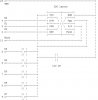
my final project contain smart card and i will interface it with Parallel port
then asssume that i make this circuit "attached"

the question now?

if i change the volt that on CLK from 0v to 5v and hold it to 5v,is the data "1st bit" will be holed at the I/O bin out?
 

Attachments

  • 1_512.jpg
    1_512.jpg
    30.2 KB · Views: 592
What kind of smart card is this? there are many diffirent ones, most of 'em contain a microcontroller (mostly a pic16f84)...

The way it acts is completely dependant on the programming of it's microcontroller.
 
i didnot get the card yet but i may use telecard or funcard or goldcard.....


if any on them will hold the data i will use it
 
I don't know about the other 2, but a goldcard contains a pic16f84 an an eeprom... So you will have to write pic software for the card. so basically it does what you want it to do.
 
Most microcontroller smart cards will come with the software already programmed in (they mask program them at the factory). The software in the card will respond to standard commands through the bidirectional uart (CIO). The communication interface is anasyncrounous bus like RS232 so the level of the clock line should have no effect (except if you keep it high the microcontroller will stop running). I don't know if Windows will be able to emulate a UART through the parrallel port. You probably would be better off using a microcontroller with a software UART.

If you want a simple solution atmel's 89c5121 is an 8051 with all the smart card interface hardware built in. You can buy them on Digikey.com.

Brent
 
tahnks for answer

but i must make it parallel port and i see more that one of programmer device work in this port, and i cannot use any program that because i will be a part of my program in will make it in Visual basic,

but look it the picture " if the data is 1 the o will out " in the case1 we will find that the data is holded untill the +ve edge come but in the next it send the data as pluse.....

is the data is out from the card as case1 or case 2?
 

Attachments

  • untitled_214.jpg
    untitled_214.jpg
    24.3 KB · Views: 550
Mohamedwaly said:
but i must make it parallel port and i see more that one of programmer device work in this port, and i cannot use any program that because i will be a part of my program in will make it in Visual basic,

As already mentioned, you need to find out what is inside the smart card, and what it's interfacing requirements are - different types are likely to be completely different. As also mentioned, PIC processors are used on quite a few smart cards, you can download the programming specifications for these from MicroChip.

Assuming your particular smart card uses a PIC processor, all you are really doing is building a PIC programmer.

If you need to be able to program different types of cards, again you need to find out their exact requirements, and write your program accordingly.
 
If you need to use the parrallel port you are probably better off using a memory card instead of a microcontroller card. Memory cards use a standard I2C interface. There should be tons of info on using the parrallel port to emulate I2C.

Brent
 
please helpi have funcard with AT90S8515 mcu and a praellel programmer"small one:4resistance+led+cap.+.."

it's my final project ,i want to make program to read the card ??

i have 8 pins
i make the followin to read it:
pin 1: vcc: 5v
pin 2:MCLR:always high"5v"
pin3"XTAL:high the low then high and so on "clock:
pin4: always low"0v"
pin5:Gnd:"0v"
pin6:NC
pin7:MISO:in input
pin8:always low"0v"


but it didnot work why?

how can i read it ?
 
Status
Not open for further replies.

Latest threads

New Articles From Microcontroller Tips

Back
Top