Electro Tech is an online community (with over 170,000 members) who enjoy talking about and building electronic circuits, projects and gadgets. To participate you need to register. Registration is free. Click here to register now.
Welcome to our site! Electro Tech is an online community (with over 170,000 members) who enjoy talking about and building electronic circuits, projects and gadgets. To participate you need to register. Registration is free. Click here to register now.
Scenerio: Have higher voltage from supply than tube's max plate specifications. Does adding another tube provide more voltage handling
capability? :shock: Thanks!!!
Hi vince,
The short answer to your question is "no". If you exceed the max plate voltage rating on tubes it can cause internal arcing of the tube and possible power supply damage as well.
You can put two tubes in a cascode configuration (search Google for "cascode tube" and "cascode tubes") to increase voltage handling capability, but if this is for an audio application (what else nowadays?), it would probably screw up the "sound" you are trying to get.
OK! Here’s what I’ve come up with breaking this down in a theoretical model :shock: .
Observing the B+ path (through the load coil to the plate and across the tube to a cathode ground) as a voltage dividing network (at fixed frequency) indicates that adding additional tubes raises the value of interelectrode output capacitance (plate to cathode) thus reducing reactance at the end of the network and increasing the voltage drop across set plate load coil.
Diverging from set frequency alters L reactance and C reactance each in opposite exponential directions changing the voltage ratio across the network.
Any thoughts :idea: ?
And thanks for the chat.
On a lighter note: Doing some quick calculations in the Audio frequency bandwidth this model would prove efficient pending music taste involving a 1khz tone… (Hearing test classics). Or… perhaps this theoretical model is applicable to RF “at” a fixed frequency. Could get lonely for a ham while waiting for someone to find him using this model…
Ron, I reviewed a few cascode circuits ! Thanks for the suggestion.
…By the way Ron, is that a mars shot (avatar) or are you into photographing solder blobs that resemble human physiognomy :shock: ? Got any dinosaurs?
OK! Here’s what I’ve come up with breaking this down in a theoretical model .
Observing the B+ path (through the load coil to the plate and across the tube to a cathode ground) as a voltage dividing network (at fixed frequency) indicates that adding additional tubes raises the value of interelectrode output capacitance (plate to cathode) thus reducing reactance at the end of the network and increasing the voltage drop across set plate load coil.
Diverging from set frequency alters L reactance and C reactance each in opposite exponential directions changing the voltage ratio across the network.
Say whut? Without a schematic, I haven't a clue what you're talking about.
On a lighter note: Doing some quick calculations in the Audio frequency bandwidth this model would prove efficient pending music taste involving a 1khz tone… (Hearing test classics). Or… perhaps this theoretical model is applicable to RF “at” a fixed frequency. Could get lonely for a ham while waiting for someone to find him using this model…
Ron, I reviewed a few cascode circuits ! Thanks for the suggestion.
…By the way Ron, is that a mars shot (avatar) or are you into photographing solder blobs that resemble human physiognomy ? Got any dinosaurs?
Yeah, it's the Face on Mars, before the "better" more recent pictures showed it to be just a hill, with no resemblance to a face. I think it's a conspiracy. :wink:
I did have a solder blob once that almost modified my human physiognomy, or at least the hand portion of it.
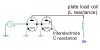
After reviewing the excerpt from my last post, yes Ron... grammatically I used "the" B+ path and “the” load coil instead of "a" path or load. Perhaps this precluded a general block diagram from being conceptualized in favor of a specific schematic I was not letting you be privy to, although your phrasing of “a” schematic may indicate you gravitate to schematics instead of mental models, fair enough Ron. Here's a quick rendering of the block model- see Attachment
Adding another tube in parallel changes the sum value of plate to cathode capacitances... say 10Pf to 20Pf... reducing the reactance by half in that stage of the network. The other stage being the plate coil.
Well, parallel tubes do increase capacitance on the plates, and they will also draw twice as much current (DC and AC), but as I understand your problem, it's a DC voltage problem. Since the load coil presumably has negligible DC resistance, the DC plate voltage on each tube is the same as before. Now you have two tubes that may overheat, or arc, or whatever.
I think cascode might work, although you might simply use a resistor between B+ and the load coil, with a bypass capacitor to ground from the junction of the resistor and the coil.
Is this an RF circuit? If so, what is the carrier frequency?
BTW, I believe the interelectrode capacitance is primarily from plate to grid. The grid shields the plate from the cathode.
In reviewing cascode circuits the voltage drops make sense.
Thanks for recomendation. I have found only triode circuits.
Have you encountered any tetrode circuits( the screens are stackin up!)
if so any ideas on configuration?
Any chance that a voltage divider circuit would help? On the surface it would seem that regulation would suffer but that might not be an issue. Could you remove windings from the transformer?
As with many things there are multiple approaches to a problem.
In reviewing cascode circuits the voltage drops make sense.
Thanks for recomendation. I have found only triode circuits.
Have you encountered any tetrode circuits( the screens are stackin up!)
if so any ideas on configuration?
The purpose of the screen grid in a tetrode is to reduce the (Miller) capacitance between the plate and the control grid, allowing higher bandwidth operation. The cascode triode configuration has the same effect. You shouldn't need to use tetrodes in a cascode circuit.
Having said that, I'm guessing that you have a schematic which uses a tetrode, and a power supply whose voltage is too high, and you don't know enough about tube circuit design to get the two together. Post a schematic and maybe we can come up with a sensible solution.
First...Thank you Ron for the exchange in this chat string, each
recomendation solves the scenerio....
Steve solves the scenerio with two logical approachs.
and Sebi... May I recomend a pillow for your keyboard(avatar)?
...In looking at my original chat post "scenerio" it seems a little nebulous as to communicating my underlying question.
I'd like a second chance to get your input-
....does a tube have a specific resistance(reactance) from plate to cathode expressed as capacitance?
If so... Does adding another tube in parallel raise the capacitance value(say... 10pf to 20pf) and reduce resistance (reactance) measured across the tubes.
And if so... does the lower reactance across the tubes change the voltage drop across the coil?
To remove any DC issues, infer full time CW operation(RF)...
Vince, I can answer your questions, but I don't think the answers will get you closer to the solution to your problem. Do you have a schematic that you are starting with? I can't believe you are designing an RF amplifier from scratch. If you do have a schematic, post it. Otherwise, we'll just beat around the bush here for days.
I get the sense your holding back on my answers...
Answers.......... You got em... I want Em.....
Clear and cogent explanations Ron....Yes...
Relax and proceed devoid of schematics and disbeliefs stemming from
working without a design or solutions to whatever "problem"(?!?) your refering to..
...think of it as improve... your a master violinist playing without a composition on the music stand....
Disregaurd my sense of humor and just let those answer fly....
This site uses cookies to help personalise content, tailor your experience and to keep you logged in if you register.
By continuing to use this site, you are consenting to our use of cookies.

 !
!