Electro Tech is an online community (with over 170,000 members) who enjoy talking about and building electronic circuits, projects and gadgets. To participate you need to register. Registration is free. Click here to register now.
Welcome to our site! Electro Tech is an online community (with over 170,000 members) who enjoy talking about and building electronic circuits, projects and gadgets. To participate you need to register. Registration is free. Click here to register now.
I need to convert a 0-10V DC output to a 0-24 V output is there a simple DC-DC converter that can do this or do I need to work with transistors or something like that.
You really need to be exact about your requirements, the existing question is far too vague - Styx may have guessed correctly?, or not?, so please give many more details of what you are wanting to do!.
I have an analogue output card that I use with an s7/300 PLC that is 0-10V and need to drive a proportional hyraulics valve that works 0-24V
The valf says maximum 1amp and the circut breaker for the output card is also 1amp.
You will need some majic or a miracle to convert 10W into 24W.
Your application doesn't need to convert anything. The 10V can turn on a relay or transistor that applies the 24V from a 24V power supply to the valve.
You know full well that an amplifier actually does no such thing, but merely produces a larger copy by modulating a higher voltage supply, or providing a larger current capability.
Not me. Styx recommended using an amplifier. I recommended using a switch.
Nigel Goodwin said:
audioguru said:
Your application doesn't need to convert anything. The 10V can turn on a relay or transistor that applies the 24V from a 24V power supply to the valve.
Surely the valve has a motor spinning gears and needs to have its power applied for a certain amount of time to control the amount of its opening.
I don't think a proportional voltage would do it, too much loss of torque at a low voltage.
Surely the valve has a motor spinning gears and needs to have its power applied for a certain amount of time to control the amount of its opening.
I don't think a proportional voltage would do it, too much loss of torque at a low voltage.
I've no idea what the valve might consist of, but he does specify 0-24V, which means 'from' zero volts 'to' 24V, as opposed to 0/24V which means a switched voltage.
As you say, if it's a simple switched 24V ON and OFF, from a switched 10V ON and OFF, then it's simple to do - presumably in normal PLC use a relay would be used?.
I have an analogue output card that I use with an s7/300 PLC that is 0-10V and need to drive a proportional hyraulics valve that works 0-24V
The valf says maximum 1amp and the circut breaker for the output card is also 1amp.
OK, that sounds like a Siemens PLC.
Can you give some detail on the valve?
A 0 to 24 volt control signal I can just about believe, but 1amp?
I could believe a 24v supply at up to 1 amp, but the control signal?
Are there separate power and control signals to the hydraulic valve?
The varying voltage supply to the valve controls the restrcition over it controling the flowrate that changes the speed of the actuators in the system. Just a proportional valve only a relay and springs no motors or such to control the opening.
with 0 to 10V I can only open it to half way that causes the machine to move slowly.
By the way another idea is to connect the two 0-10V outputs of the analogue output card in series, then do I have 0-20V to control or do I damage the equipment?
This site uses cookies to help personalise content, tailor your experience and to keep you logged in if you register.
By continuing to use this site, you are consenting to our use of cookies.

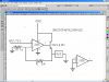
 C converter, but a amplification