ADWSystems
Member
Now that I'm a "genius", the boss thinks that I remember how to do this stuff because I did it 10-12 years ago. Any how, I digress.
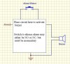
The boss was to modify a piece of equipment to add a remote announciator (buzzer) with a silence button. The trick is the silence button. The only signals I have access to will be ground and the buzzer power, no constant power source (Vcc) via optocoupler or relay contact output. The button is to be momentary so no one can turn it off and forget to turn it back on.
My initial thoughts are to convert the always on output to a one-shot output to latch a relay with a NC switch to unlatch it. The relay and buzzer and can draw their power from the incoming voltage. I need a one shot circuit that doesn't require a constant power source (Vcc). So that rules out most ICs (555, etc.) and I'll need to go straight analog.
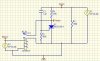
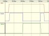
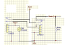
I was thinking of using a PN2907a with a RC net on the base, the emitter tied to the incoming power, and the collector tied to one side of the relay coil. The incoming signal will go through the resistor to the base and cap (the the cap connected to ground on the other side). The resistor will limit the current to the base and capacitor, making a nice RC time constant (I hope). I think a 100mSec second pulse will be enough to engage the relay. After the cap is charged, the collector will stop flowing current. Will the capacitor supply too much current to the base and blow the transistor?
If anyone has any other thoughts I'm open to suggestions.
P.S. I will try to get the schematic editor working again and see if I can post my idea.
The boss was to modify a piece of equipment to add a remote announciator (buzzer) with a silence button. The trick is the silence button. The only signals I have access to will be ground and the buzzer power, no constant power source (Vcc) via optocoupler or relay contact output. The button is to be momentary so no one can turn it off and forget to turn it back on.
My initial thoughts are to convert the always on output to a one-shot output to latch a relay with a NC switch to unlatch it. The relay and buzzer and can draw their power from the incoming voltage. I need a one shot circuit that doesn't require a constant power source (Vcc). So that rules out most ICs (555, etc.) and I'll need to go straight analog.
I was thinking of using a PN2907a with a RC net on the base, the emitter tied to the incoming power, and the collector tied to one side of the relay coil. The incoming signal will go through the resistor to the base and cap (the the cap connected to ground on the other side). The resistor will limit the current to the base and capacitor, making a nice RC time constant (I hope). I think a 100mSec second pulse will be enough to engage the relay. After the cap is charged, the collector will stop flowing current. Will the capacitor supply too much current to the base and blow the transistor?
If anyone has any other thoughts I'm open to suggestions.
P.S. I will try to get the schematic editor working again and see if I can post my idea.

")
