Continue to Site

Welcome to our site!

Electro Tech is an online community (with over 170,000 members) who enjoy talking about and building electronic circuits, projects and gadgets. To participate you need to register. Registration is free. Click here to register now.

  • Welcome to our site! Electro Tech is an online community (with over 170,000 members) who enjoy talking about and building electronic circuits, projects and gadgets. To participate you need to register. Registration is free. Click here to register now.

Amplifying sound output with LM386

Status
Not open for further replies.

mik3ca

Member
circuit.png


In my application I play sound clips from the ISD1700 series soundcard. Before I started this amplifier add-on, I tried to hook earphones directly to pin 13 and 15 to the chip to hear sound from the on-board sound port. The volume is acceptable, but when I used an 8-ohm speaker, the volume is low, however I configured the chip to run at max volume and to ignore the VOL pin.

I read up in their manual that one can attach a transistor to amplify the sound, but I want to make loud sound that can be heard from the other end of the room.

I first tried connecting earphones directly to AUD/AUX pin of the soundchip in series with a 22uF capacitor and the sound volume was so low I could almost not understand it.

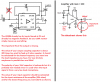
So I pull out my LM386 amplifier because it has amplified radio signals for me in the past and I tried it with the analog output of the sound chip as shown above, and even though the amplifier amplified the sound somewhat, it seems to still be at lower volume than what I could get if I hooked up the earphone directly to pins 13 and 15 of the soundchip.

I'm afraid if I hooked the output of pin 13 or 15 to the amplifier input, I might blow something up.

Now during tests, if I remove the resistor and disconnect pin 17 from the amplifier then as I hold the wire I hear a loud buzz which suggests to me the LM386 knows how to amplify faint sound.

Is there something I can do to improve volume of the sound using the same kind of circuit? I'm willing to add more commands through the SPI interface if that makes the world a difference.

P.S. the coupling capacitors I use is 0.047uF and I intentionally not connected anything to other parts of the ISD soundchip as they weren't relevant to the question.

Now when I did testing, I used a breadboard for the amplifier part of the circuit. The soundchip section is all on PCB. and the power supply I used is 5VDC
 
At 5 Vdc, the 386 can barely make 1 W into an 8 ohm load.

What is the purpose of the 100K resistor from the output to the - input? The datasheet has audio amplification application circuits, and none of them have this (IIR). The 386 is not a normal opamp, and does not use an external feedback resistor to set the gain.

The 386 *must* have decoupling capacitance near the power and ground pins. Also, your schematic does not show the Zobel network on the output.

Post the datasheet for the ISD chip.

ak
 
Here's the ISD datasheet http://www.microtechnica.tv/support/manual/ISD1700_Design_Guide.pdf

and I was using resistor as feedback. I guess I can omit it.

I did try a 100uF decoupling capacitor after and all I heard was distortion. Without the capacitor I could hear the sound but too quiet. I wonder if my only solution is to ditch the breadboard and go PCB only with short tracks. I wonder if the long wires to power are the problem because sometimes when I use a breadboard I could get carried away with long wires.
 
It looks like you did not read the datasheet of the LM386 power amp because your schematic is completely wrong.

Did you know that the maximum output power of the ISC1700 is actually about 3 times higher than the max output power of the LM386 when they both use a 5V supply and an 8 ohm speaker? Because the ISC1700 drives both speaker wires with signal so the voltage swing is doubled then the current swing is also doubled.

Try the schematic I am posting with the Aux Out of the ISD1700 feeding the input capacitor of my LM386 schematic. Then try the ISD1700 feeding an 8 ohm speaker as shown on its datasheet to see that it is louder.
 

Attachments

  • LM386.png
    LM386.png
    50.4 KB · Views: 317
I tried once reversing + and - inputs like you mentioned with less favorable results but I'll look into the other steps you mentioned. and does that shunting capacitor/resistor network you circled reduce gain somewhat too? Then again I was using a breadboard for the amplifier tests.
 
I also tried a 100uF at the output instead of 2.2uF and sometimes it seemed that I had to wait for the capacitor to charge up before I could hear sound (while missing the beginning of it). this was after I instructed ISD1700 to play audio.
 
Since the LM386 has an internal gain of 10 and a 50k input resistance to ground then your 100k resistor was trying to make inverting the input voltage positive that reduces the output voltage that is supposed to be at half the supply voltage. Then the output will be very distorted.

The 10uF capacitor between pin 1 and pin 8 makes the AC gain 200 times that causes severe distortion when the ISD1700 feeds it a 1V peak to peak signal. Even if the LM386 has the gain reduced to 10 by removing your 10uF capacitor then the gain is still too high and will cause severe distortion unless the volume is reduced. The datasheet for the ISD1700 does not say if the Aux Out level is changed with its volume control.
 
So my answer then is to remove the 10uF gain cap and lower the ISD volume? I wonder if I can get good results with this amp if I replaced the 100K resistor with some sort of capacitor.
 
The input signal can feed either the + input or the - input then both will sound the same. But usually the + input is used.

The zobel RC network at the output prevents oscillation at a high frequency (which causes severe distortion and heating) and has nothing to do with audio gain.

I said that the output capacitor value must be calculated for the impedance it is feeding.
You said a 100uF output capacitor took time to charge. The math of its charging time is 100uF x 8 ohms= 800us (0.0008 seconds which is almost nothing). If it feeds something with a 100k resistance then its charging time is 100uF x 100k= 10 seconds.
 
Why on earth do you want to add negative feedback to the LM386 with a capacitor? The datasheet of the LM386 that you did not read says it is unstable (it will oscillate at a high frequency and produce severe distortion and lots of heating) if you reduce its gain below 9 times.

Why do you want to use the LM386 amplifier when the amplifier in the ISD1700 produces about 3 times more output power??
 
I'm not sure how to configure RC in zobel. I'm guessing I should treat it as an audio high-pass filter. but when I did math, I got a value between 300Khz and 2Mhz (I tried 1/(2pi*rc) and 1/(rc)).
 
Why do you want to use the LM386 amplifier when the amplifier in the ISD1700 produces about 3 times more output power?

It didn't seem that way, and plus as I said, I want to create loud sound that can fill a room. The ISD wasn't able to do that by itself.
 
I'm not sure how to configure RC in zobel. I'm guessing I should treat it as an audio high-pass filter. but when I did math, I got a value between 300Khz and 2Mhz (I tried 1/(2pi*rc) and 1/(rc)).
An applications note for an LM380 (similar to an LM386) amplifier says some details about the output zobel network. Without it the oscillation is at a low radio frequency. Since the LM386 has plenty of gain at frequencies higher than 1MHz then an input wire near an output wire or the mess of wiring on a solderless breadboard can cause oscillation even with the zobel network.

One reason that the zobel is needed is that the amplifier is stable when loaded but a speaker is inductive and is not a load at a radio frequency.
 
It didn't seem that way, and plus as I said, I want to create loud sound that can fill a room. The ISD wasn't able to do that by itself.
The datasheet for the ISD1700 says that its maximum output power is about 0.6W with a 5V supply and an 8 ohm speaker.
The datasheet for the LM386 with the same supply and speaker says less than 0.2W.
Don't you think that 0.6W is louder than 0.2W??

The speaker on the ISD1700 has both its wires fed with signal if the speaker is connected as shown on its datasheet. The speaker on an LM386 amplifier has only one of its speaker wires fed a signal then the voltage swing is half and the current swing is also half.
 
I was using resistor as feedback. I guess I can omit it..
Given the clarity of the applications circuits and text in the datasheet, why did you think this resistor was necessary? Also, how did you arrive at the 100K value?

ak
 
circuit.png


I guess if the LM386 is meant to provide worse performance then I'm considering redoing my PCB layout to accommodate for the above circuit instead. I took the idea from Harry's homebrew transistor biasing at **broken link removed**

would such a design be able to amplify the sound from the ISD chip? and are the TIP31/TIP32 transistors good enough to add sound volume or do I need transistors with higher rating? and I'm still using 5VDC for power.
 
The 3 transistors circuit will be only slightly better than an LM386 if they both have the same very low voltage power supply. But it is missing a very important input coupling capacitor (shown in Harry's article) to block the 1.2V DC on the Aux output of the ISD1700. Without the capacitor then the amplifier will amplify the DC and cause almost no output except bursts of severe distortion at the loudest signals.
Two diodes (shown in Harry's article) match the base-emitter diodes of the output transistors to cancel crossover distortion (look at it in Google) that occurs with no diodes or only one diode.

You need to understand about loudness and amplifier power. The loudest sounds are louder when an amplifier produces a higher maximum output power. Amplifier power is the RMS voltage swing at the output squared, then divided by the speaker impedance.
Your power supply is only 5V then the output swing of the LM386 as shown on a graph on its datasheet is 3V peak to peak which is 1.06V RMS. Then the maximum undistorted power intro an 8 ohm speaker is only 0.15W which is almost nothing but fine for headphones. If the amplifier supply voltage is 9V then the power is 0.56W. Harry's circuit has a little more power than an LM386 because it has R1 and C2 to bootstrap the signal driving the base of the NPN output transistor so then its output power is about 0.22W which is only slightly louder than an LM386.

The ISD1700 drives both wires of the speaker so the voltage swing at the speaker is doubled. Two LM386 amplifiers or two of Harry's amplifiers will produce about 0.6W on the speaker the same as the amplifier ion the ISD1700.
 
So I guess the LM386 idea is useless? And if I took on harry's circuit, could I lower resistance values and use more powerful transistors like the TIP31/TIP32 to produce more output power and volume with the same voltage? (man I'm gonna have a funny circuit board after this)
 
Status
Not open for further replies.

Latest threads

New Articles From Microcontroller Tips

Back
Top