Continue to Site

Welcome to our site!

Electro Tech is an online community (with over 170,000 members) who enjoy talking about and building electronic circuits, projects and gadgets. To participate you need to register. Registration is free. Click here to register now.

  • Welcome to our site! Electro Tech is an online community (with over 170,000 members) who enjoy talking about and building electronic circuits, projects and gadgets. To participate you need to register. Registration is free. Click here to register now.

Amplifying an automotive tach signal

Status
Not open for further replies.

ant

New Member
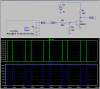
I'm trying to get the rev counter working on my current car project. My output comes from the ECU & is a 4-5v signal (I don't have the equipment to test frequency). My tacho requires a 12v signal (it was triggered from the coil originally). I have built a circuit to try and amplify the signal but it doesn't work & I have exceeded my electronics know how. Here is a pic of the circuit -
**broken link removed**
I'm getting a fluctuating 4-5v in and a steady 4v output. This is all DC.
 
You are trying to get a relay to follow the Tach pulse rate, which it cannot do. It takes ~20ms for relay coil to pull-in and up to 100ms for it to release.

Try this:
 

Attachments

  • DF89.png
    DF89.png
    30 KB · Views: 2,005
Last edited:
What you need to do is give us the diagram of the original tach circuit (or what car it's from).

There's a good chance your factory tach is expecting a much higher voltage than 12V (mainly because of the high voltage spike that occurs when the coil discharges) and the tach has a circuit to reduce this. Feeding this type of tach 12V may not be enough for it to work properly.

What I've done in the past is use a small inductor in conjunction with a transistor the charge it in order to generate a high-voltage spike and get my tach to fire off a 5V signal from an ECU.
 
Thanks for the replies. Only the coil from the relay is used, all the 'mechanical' parts have been removed so I have it wired directly to the coil. It was convenient to put the circuit in a relay case.

The circuit diagram for the original consists of a wire that goes from the coil straight to the rev counter. COIL---------TACHO thats it! The car is a Mk2 vw golf which is now fitted with a different engine, using a 5v triggered wasted spark coilpack.

eta:mikeml, the circuit I have made is very similar to the one you have pictured, mine has no R2, R1 is replaced by the relay coil. What function does R2 have?
 
Last edited:
R2 is there to make sure that the transistor turns off correctly and quickly when the input is low. It may not be needed, but it can't hurt.

Your relay coil may well produce spikes that trigger the rev counter, but there is a danger that you could damage the transistor, which is rated to 160 V or so. You should put a resistor in parallel with the coil. Chose a value about 10 times the resistance of the coil and you should limit the voltage spikes to about 120 V.

There is no guarantee that the tacho will read correctly once you get the correct signal through. The wasted spark ignition systems that I have seen used two coils for a 4 cylinder engine, so each coil was triggered at half the rate that a distributor system would have been triggered at.

If there is a single coil pack with 4 outputs, the 5 V signal to it could be just about anything.

You could also run the tacho off the AC output from the alternator. That usually needs opening up to add a wire to access the AC direct from the coils, before the rectifier, and the frequency won't be the same as the spark frequency, but it will work on just about any car.
 
So do I actually need the relay coil at all?

I originally had a 'normal' wasted spark setup (4 cylinder, 2 pairs of coils, the ecu has 2 coil drivers) which was earth triggered. I took the rpm signal from the earth wires, through 3 diodes to halve the signal & straight into the tacho. The new coil uses a +5v trigger so I cannot use it to run the tacho, however my ecu has an rpm output. The ecu can halve / double the output so I should be able to use it to run the tacho. I hadn't considered the alternator output...
 
So do I actually need the relay coil at all? ...

I'm assuming not. The tachs designed for point-coil ignitions have a filter to get rid of the inductive spikes which naturally occur across the coil primary when the points open. However, if you feed them with a clean 12V pulse from a laboratory signal generator, they indicate the correct RPM. They generally dont care what the duty cycle of the pulse is; anything from about 10% to 90% seems to work just fine. The circuit I posted is just a simple amplifier; it makes a 12V pulse out of a 4V pulse.

Here are some previous threads about Tach pickups for points ignitions:

Thread 1

Thread2
 
All,

I am trying to do the same thing. I have a 1968 BMW 2002 that was originally a coil / points system. I'd like to use my original Tachometer (uses the high voltage spikes). My Megasquirt 3 +MS3X outputs a 12V square wave with 50% duty cycle. I would like to amplify the signal to make the tachometer work. The links listed above seem to do the opposite, take a high voltage signal and turn it into a 12V square wave. Am I reading that correctly?

Much thanks

Chris
 
I understand what this circuit is doing now. The coil is used for tachometers that are expecting a high voltage.

**broken link removed**

MSnS-Extra Hardware Manual

Unfortunately it is hit or miss if the particular relay has a coil that is wound enough to make this circuit work. Is there somebody that can help spec out a coil or inductor that would work here?

I used a coil in order to make my old digital ignition work. It was awfully large, I'd hope it wouldn't need to be this big.

**broken link removed**
 
Just a quick update on my (slow) progress with this. In my defence I have rebuilt a Porsche 944 in the interim. I have since tried another circuit without the coil - this didn't work. Recently I have built another with the coil, this worked perfectly initially but the output became weaker & weaker before failing, took around 20 mins. I have checked it on a scope & have a healthy 5v output from the ecu (normally high) but the transistor has failed. So is there a way to protect the tranny? I dont have an option to make the output normally low (although may be able to find a suitable feed in the ecu) but I'd think being normally low would overheat the coil?

eta: just reread the thread, diver300's suggestion regarding the resistor in parallel sounds promising. I'll give it a go.
 
Last edited:
Status
Not open for further replies.

Latest threads

Back
Top