Continue to Site

Welcome to our site!

Electro Tech is an online community (with over 170,000 members) who enjoy talking about and building electronic circuits, projects and gadgets. To participate you need to register. Registration is free. Click here to register now.

  • Welcome to our site! Electro Tech is an online community (with over 170,000 members) who enjoy talking about and building electronic circuits, projects and gadgets. To participate you need to register. Registration is free. Click here to register now.

Amplification of the signal decay

Status
Not open for further replies.

hesam_m

Member
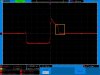
I should amplify a low impedance signal with the peak of maximum 1.4V.

The tricky part is that the signal itself is not important but the tail of the signal is important which might show some decay (falling edge could reach to zero sooner or later than normal) and these signal decay variations are very small (a few microvolts)

The thing is if I amplify the whole signal by a typical opamp, it easily sticks to the supply rails and clipped. because the signal itself is not small but its decay is very small.

The application is the battery powered and the single supply design is preferred.

is there any way to just amplify the variations?
 
This can be done.
I need to know more about the signal. Starts at 0 vlots? Then 1.5v pulse. Then comes back to 0 volts? You do not care about the signal above 0.5v? You want to see clearly the signal form 0 to 0.5? How much gain? What power supplies? Is there a negative supply?
 
I think he wants a controled clipping that is not done by driving into the supply, where the amp gets slow sns sticky.
 
Let me add a picture of the signal.
The yellow rectangle shows the tail which might show the decay variations.
if I amplify the whole signal or even the yellow part (clipping it by a digital switch or something), the wave will stick to the rails, because of the high gain.
if I select a low gain, then the variations will not be detectable.

it's tricky.
 

Attachments

  • zc67_bk4_20131005_041826.jpg
    zc67_bk4_20131005_041826.jpg
    87.9 KB · Views: 253
The microphone in the AGC circuit is not a condenser type that needs a 48V power supply, instead it is an electret type that has the 48V stored permanently in its electret material. An electret mic has a Jfet impedance converter in it that draws 0.5mA then the 10k resistor powering it has a value twice what is needed, the 10k will cause the mic to be distorted.

The BC548 transistor preamp is biased completely wrong. If its hFE is minimum near 110 then it is cutoff and distorted. If the hFE is near maximum at 800 then it is saturated and distorted. The one demo'd is simply lucky to have a medium hFE of about 264. But the transistor has an input impedance of about 4k that loads down the mic signal.

A lousy old 741 opamp is never used for audio.
 
audioguru: I guess my link is not such a great example.:oops:

And I agree. I'd use a TL082 as an amp, and a jfet in the feedback loop inversly controlling the gain.

I'm wondering about the negative pulse at the beginning of the waveform and if it can be removed or at least minimized.
That would make it easier to rectify the signal and lower the gain accordingly.
 
I'm wondering about the negative pulse at the beginning of the waveform and if it can be removed or at least minimized.
That would make it easier to rectify the signal and lower the gain accordingly.

There is no negative part. the lowest is 0 volt. that's the signal or screen shift.
So as the result your suggestion is the AGC? can it be used with low impedance sources and single supply?
 
Assume the only power supply is +5V. (V3)
Signal is V1.
V2 is a bias set for 0.7V. (could divide 5V down to make this)
This op-amp is R-R only 2mhz and low voltage. I chose CMOS R-R because there is no negative supply and they are good at coming off being over driven.
1547937807880.png

The way it is set any voltage below 0.7V produces 0V. (output slams into ground but I think that will be fine)
Voltages from 0.7 to 2V produce a 0 to 4.3V output. Note I tried to keep the peak away from 5V.
Gain =3.3x
The amp is a little slow because I did not know the speed when I drew this.
 
May I ask you how this circuit could help me? besides, I think this circuit should have a cap in the input
 
No capacitor. That would only let the AC part of the signal through.

This circuit: out=3.3 x (V1-V2)
The signal is shifted doen 0.7 volts so most of what you don't care about is below ground. Then gain of 3.3x. Any thing negative is lost.

Amp is R-R, "rail to rail" type. It works with signals neat/at its supply.
 
Your signal appears to have more than "micro volts" of noise so maybe not.
Is the 0.8 volt level stable to uV? So 0.800,000 is good and you want to know when the signal crosses 0.800,001. But if the 0.8 moves any amount from one month to another then it will not work.

Forget the opamp and move to a comparator. Signal on one input and 0.801 volts on the other. That only gets you to mV. A comparator gets real slow with the differential is small.

Two signals that have a differences at uV will also have a differences at mV levels.
 
from the beginning many times I mentioned that the signal is not important for me but the decay of the signal is, which shows very small variations. BUT because the signal itself has a high amplitude, it is difficult to amplify it, because it easily goes to the rails. This hides the variations.
Thank you for the contribution but it seems you read the texts fast or I could not convey the meaning.
 
A voltage comparator IC will not care about over drive. Its output will be 1 or 0 (high or low) depending on if V1 is above V2. They can resolve mV but probably not uV. I did not respond to "uV" because that is very hard in the face of noise and temperature changes.

I have made several pieces of test equipment that looks at a very similar wave form and resolve the time to return back to "0.8V". I measured the "return back to 0" at 10mV or 1mV levels because 1uV is not easy. Your o-scope can not see uV and will struggle to see mV but you can see what you want on the scope.
 
They can resolve mV but probably not uV
That's True

Your o-scope cannot see uV and will struggle to see mV but you can see what you want on the scope.

That's True, but I can make the decay strong enough to be detectable by the oscilloscope. that's not the problem now. for this task, just the detection is not enough but I have to read the decay (for example by an ADC) and measure its variations.
No problem about the noise because the signal and noise will be amplified both but when the decay is present, it is obvious. but it should be high enough to be detectable. therefore 3.3x gain is very low.

The introduced AGC idea looks interesting either
 
I was trying to set the input of your ADC to span this area: 0 to 5V full scale.
1548004569794.png

By changing the two 33k to 68k you will see this on the ADC input. 0 to 5V
1548004631994.png

If this is more like what you want then I will have to add a circuit that allows the amplifier to come off of +5V faster.
1548004837148.png

Long before uVs you will see this. Where is 0.800001?
1548004966824.png
 
I was doing some thing like this to VGA video. The pulse was 35mhz. Fast.
Because of noise and instability we measured 10 pulses and found the average high and average low level and in software declared that to be 100% and 0%. (some thing like AGC)
At those speeds I could not see mV and certainly not uV. In my case we set points at 90% and 10% but your upper level looks like 80% might be better. [in your case I think you will measure from upward edge to falling slope at some level]
We measured the time from 90% to 10%. Through experimenting we found that 90 to 10 gave us the best results. Measuring to 1% resulted in every measurement being different. Measuring to 0.01% would give very noisy measurements. (measure where the slope is steep to avoid noise)
1548006828867.png

Probably you can not measure very fast so you want to measure down to uV so you have more time.
 
Status
Not open for further replies.

Latest threads

New Articles From Microcontroller Tips

Back
Top