Continue to Site

Welcome to our site!

Electro Tech is an online community (with over 170,000 members) who enjoy talking about and building electronic circuits, projects and gadgets. To participate you need to register. Registration is free. Click here to register now.

  • Welcome to our site! Electro Tech is an online community (with over 170,000 members) who enjoy talking about and building electronic circuits, projects and gadgets. To participate you need to register. Registration is free. Click here to register now.

AM Transmitter and Receiver Help

Status
Not open for further replies.

arustu

New Member
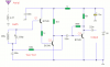
I require help with the following schematics of AM TX/RX ckts. I have tried to construct it the way it is shown with only slight changes:

- Instead of a 500pF variable capacitor, I have used a capacitor which can vary from 147pF to 12pF
- Instead of a BC109C, I haver used a BC109B transistor.

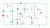
The problem is that after the voltage is applied, I dont get any output at the speaker end. Upon measuring the voltage on the speaker, I found that there was NO voltage across it.(I have a 0.5W, 16 ohm speaker)

Also, the voltage across the antennae on the TX side is the entire supply voltage ie 9V. Is that suppose to happen?

The schematics of both TX and RX are attached with this post.
 

Attachments

  • amrx.png
    amrx.png
    7.3 KB · Views: 285
  • amtx.gif
    amtx.gif
    7 KB · Views: 231
Hi
forget the Rx--try to use any available radio with Medium wave --keep at, say, 700 KHz-- now if needed add a 330pF parallel to 12-147pF capacitor-
play voice thro a tape player or cd player before the mic-- now try use a head phone with radio(otherwise you are likely to get misled by direct voice coming from the player- slowly tune the 12-147 cap to be able to listen on the radio-- if needed reduce the paralle cap to say 120pF-- etc try patiently
 
The transmitter's antenna must be very long for the range to be max. This is an old AM radio system and their transmitting antennas are huge.

The receiver doesn't have a speaker power amplifier so it won't make much sound in a speaker. Also the value of the output capacitor is far too low for a low impedance speaker.

Of course the transmitter's antenna measures 9VDC. It is connected directly to the battery though the inductor.
 
Thanx Mr sarma...i think ill try out ur parallel capacitor tip.

Btw, audioguru...you think too that i shud forget about the RX ckt? Will an LM386 be suitable enough for the speaker?
 
The receiver doesn't have an AM detector so it might not work.
It doesn't have automatic-gain-control so if it works then it will be either too loud or too weak.
If there are many AM radio stations then since it has only a single tuned circuit then it will mix them and play most of them at the same time.

An LM386 amplifier will allow it have the same volume as a clock radio if the signal is strong (a long antenna and earth ground).
 
audioguru said:
The receiver doesn't have an AM detector so it might not work.
I think it uses the nonlinearities in the transistors to do the detection and it's a pretty crude way of doing it.
 
It is nice to build a receiver using transistor as a detector. here the attention, perhps is being able to achieve transmission- thus to reduce project time it would be better to depend on a readily available receiver with am band and when the Tx is copleted one can always try realise a Rx. for test purpose keep one item as known good.
 
Status
Not open for further replies.

Latest threads

New Articles From Microcontroller Tips

Back
Top