Continue to Site

Welcome to our site!

Electro Tech is an online community (with over 170,000 members) who enjoy talking about and building electronic circuits, projects and gadgets. To participate you need to register. Registration is free. Click here to register now.

  • Welcome to our site! Electro Tech is an online community (with over 170,000 members) who enjoy talking about and building electronic circuits, projects and gadgets. To participate you need to register. Registration is free. Click here to register now.

Air Conditioner Remote Control

Status
Not open for further replies.
Back on topic - I wonder what the OPs Air Conditioner IR Remote Carrier frequency is?

As I also mentioned above, it seems to make little difference - at least with 36/38/40KHz - possibly 56KHz might be more of an issue?, and the crazy 100KHz that B&O used is so far out as to unlikely to work, just as no Universal controls supported it.
 
Does not look like any protocol I have ever seen.

Unless somebody else can spot a known protocol, then I guess you will have to write your own code to handle it.

Note that IR 3-pin receiver modules usually distort the transmitted signal (and by different amounts depending on range). If memory serves, marks are elongated and spaces shortened a little. For example, your 0.45 high - 1.6 low may actually be transmitted as perhaps 0.5 high and 1.5 low - ie regular timing units (t= approx 0.5 mS) of 1t high, 3t low.

I think that is me out of ideas for now.... good luck

EDIT: Oh.... or else just use a universal remote with learning capability. Not that any remote is truly universal. What we don't know yet is the modulation frequency used by your Air Conditioner remote control. 36, 38 or 40kHz are all easily handled by most learning remotes. 56 kHz is handled by many remotes, but not all. Other frequencies might only be handled by the most expensive remote controls.

What I have noticed is that "learned" messages are often not transmitted as reliably as the original remote transmitted signal. I tend to write my own code to more accurately transmit an accurate message, but then I am lucky that I have a lot of resources, understanding and interest.

What I have never achieved is making a remote as nice as commercial remote controls. Battery life on home made remote is severely limited. Best result I ever achieved was by building a receiver/transmitter that recognised spare buttons on my TV remote and then re-transmitted a different bespoke message to a foreign device (in my case a TV with lost remote). Even this was not ideal, as there has to be a delay between receiving and re-transmitting. Repeat codes were not catered for (such as holding down vol+ to give smooth volume increase.

Hello again,


No problem with the IR 3 pin receive module, i am using a pin photo diode...real fast and picks up the carrier too, which BTW looks like 40kHz for this unit. The delay with this kind of diode is on the order of 5 nanoseconds.

I was going to try the universal remote, which does do 56kHz BTW, but i did not have a manufacturers code for the AC unit. The data sheet only shows TV's and other enetertainment devices like DVR's etc.
There is a way to 'hunt' for the code using the remote, but i did not get around to trying that yet.

As far as battery life, if you havent noticed yet, the game is all about efficiency and device duty cycle.
The efficiency is hard to adjust with a remote because of the battery voltage vs LED voltage, but the duty cycle
can be adjusted quite extensively by using the watchdog timer. The watchdog timer is set, then the microcontroller
is put to sleep. When the time expires the uC wakes up and in the interrupt routine you do a scan of the keys,
noting if ANY key is pressed, and if so, scan again to read the key, but if no key then set the timer again and
put back to sleep again. You can get the 'awake' duty cycle down very very low, such that the battery life
is extended into the years when the remote is not being used. Of course this requires a uC chip such as a PIC
that uses micropower or nanopower when put to sleep. My fridge monitor gets 2 years on two AA size alkaline
batteries. When a remote is transmitting, it must use power, no way around that, but with the timer sleep
schedual the remote will look like a commercial unit which only needs battery replacement now and then.

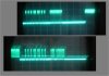
Here are some lousy scope pictures, but they show the actual measurements. The camera was hard to hold still.
You can see the pin photo diode picks up the carrier too, but with this time scale shows up as a blur.
The two traces show pulses picked up for two different buttons pushed.
 

Attachments

  • GE_AC_RemoteCodeScopePulses_5msPerDiv-1.jpg
    GE_AC_RemoteCodeScopePulses_5msPerDiv-1.jpg
    68.5 KB · Views: 210
Hi again

Little update...

I got a TSOP13xx type IR receiver, 40kHz this time, and it reads the remotes really nicely. I can get fairly clean signals now without any filtering. It seems to work on the 38kHz remote too, and i will be checking others as well.
Price was really good too, under a dollar USD.

The codes for the AC are definitely not like any of the other remotes, but then the other remotes all have their own technique anyway. I dont have one remote that has the same format as any other no matter what devices they came from.
 
yaya, the tsop i have inverts the signal, so I may get this backwards but it seems to me that the main thing to look at is the on times and off times for the start pulses and the data logic 1 pulses and logic 0 pulses as well as maybe the pulse off time between the bits....

if the timing for those match up , then it would be no problem getting a universal remote to do any device....providing that we can upload a whole code map on universal remote , this is not to be confused with the 3-4 digit code you normally type in the remote to call code map
 
Hi,

I dont know exactly how the universal remotes do it though. I wonder if the 'learning' ones store the actual timings or look it up in a table.
I could imagine making one that reads the pulses and then just duplicates it, but not sure if that would work or not.
 
I could imagine making one that reads the pulses and then just duplicates it, but not sure if that would work or not.

Of course it would work, why wouldn't it? - it's simply duplicating the existing signal.

Regardless of how it's actually transmitted you can easily store commands as binary - not as the actual binary data of the commands, but as a binary representation of the pulses transmitted. As I've always said in these threads, it's easiest (and best) to do it in software, rather than using hardware PWM modules, it's more accurate and provides exact numbers of modulation pulses as the original does.

Here's a piece of code from a project I built for a friend, it continually transmits the 'backup' code for a Sky remote, using Philips RC6 code.

Code:
Transmit
     MOVLW   0x0F       ;send preamble
     call   Xmit_RS232
     MOVLW   0xCA
     call   Xmit_RS232
     MOVLW   0x93
     call   Xmit_RS232
     MOVLW   0x55
     call   Xmit_RS232
     MOVLW   0x55
     call   Xmit_RS232
     MOVLW   0x55
     call   Xmit_RS232
             ;end of preamble
     MOVLW   0x95       ;send backup codes
     call   Xmit_RS232
     MOVLW   0x5A
     call   Xmit_RS232
     
     movlw   d'40'       ;delay approx 10 secs (40x255mS)
     call   Delay255
     goto   Transmit
 
Of course it would work, why wouldn't it? - it's simply duplicating the existing signal.

Regardless of how it's actually transmitted you can easily store commands as binary - not as the actual binary data of the commands, but as a binary representation of the pulses transmitted. As I've always said in these threads, it's easiest (and best) to do it in software, rather than using hardware PWM modules, it's more accurate and provides exact numbers of modulation pulses as the original does.

Here's a piece of code from a project I built for a friend, it continually transmits the 'backup' code for a Sky remote, using Philips RC6 code.

Code:
Transmit
     MOVLW   0x0F       ;send preamble
     call   Xmit_RS232
     MOVLW   0xCA
     call   Xmit_RS232
     MOVLW   0x93
     call   Xmit_RS232
     MOVLW   0x55
     call   Xmit_RS232
     MOVLW   0x55
     call   Xmit_RS232
     MOVLW   0x55
     call   Xmit_RS232
             ;end of preamble
     MOVLW   0x95       ;send backup codes
     call   Xmit_RS232
     MOVLW   0x5A
     call   Xmit_RS232
  
     movlw   d'40'       ;delay approx 10 secs (40x255mS)
     call   Delay255
     goto   Transmit


Hello Nigel,

Why might it not work?

For one, i havent tried it yet.
Secondly, there is a delay in the output of the module when a burst of light pulses are presented to the input pin diode. How much delay i cant be sure yet, but i will eventually measure that. The delay misses part of the pulse so the pulse seems shorter.
On the data sheet they are a little unclear about the delay, so i will have to measure it myself. If it is small enough it may not matter but i dont know that information yet. They do specify a min of about 10 cycles of the carrier for a burst.
If the delay 'on' is the same as 'off' then the burst will show up as the same width as the light pulse burst, but if different it will show up as a shorter pulse.

The only remote i made in the past was a remote that sends out codes like yours did, but it did not have to read anything. The pulses and carrier were determined by using a pin photo diode with 5ns response time and that picks up everything very fast. Once determined with that, i was able to generate the pulses because i knew the exact length of the required bursts, and of course the carrier frequency.

Yes i would store the binary burst information not every individual carrier pulse :)

I have to break out the scope again anyway to measure the carrier frequency on the cable box as for some reason i did not write that down anywhere when i did it several years back. I was going to build a remote but it takes a lot of buttons and i dont want to double or triple function them all.
 
Hello Nigel,

Why might it not work?

For one, i havent tried it yet.
Secondly, there is a delay in the output of the module when a burst of light pulses are presented to the input pin diode. How much delay i cant be sure yet, but i will eventually measure that. The delay misses part of the pulse so the pulse seems shorter.
On the data sheet they are a little unclear about the delay, so i will have to measure it myself. If it is small enough it may not matter but i dont know that information yet. They do specify a min of about 10 cycles of the carrier for a burst.

As I've explained endlessly, it doesn't matter - you just need to replicate the output from the TSOP - the changes in pulse width are of no consequence, that's why IR (and radio) remotes use various coding schemes.
 
As I've explained endlessly, it doesn't matter - you just need to replicate the output from the TSOP - the changes in pulse width are of no consequence, that's why IR (and radio) remotes use various coding schemes.

Hi Nigel,

Thanks that is useful information there.

Do you happen to know what the limit might be?
In other words, if the pulse burst is supposed to be 500us long and gets shortened to 250us, will it still work?
In other words, what is the tolerance?
 
Hi Nigel,

Thanks that is useful information there.

Do you happen to know what the limit might be?
In other words, if the pulse burst is supposed to be 500us long and gets shortened to 250us, will it still work?
In other words, what is the tolerance?

I've no idea, but suggesting ludicrous variations doesn't help :D

As I've said, yet again, as long as you duplicate the output of a TSOP you've no problem.
 
Hi,

Well, it may very well take a 250us pulse that's why i said that, to help establish some limits. Ludicrous would be 10us :)

But ok then, maybe what i will do is build a repeater and see how well it communicates. That's the simplest test i can think of.
Maybe a transistor driven by the TSOP receiver, gating the carrier, driving the IR LED. I actually wanted to build a repeater too for a long time now and never got around to it. I may end up going back to the lone pin diode though because that wont require an oscillator and also will do all my remotes, while the 40kHz TSOP wont work at 100kHz very well.
 
Hello again,

I finally got back to this 'project' and found that the Sony universal remote with 'learning' can actually learn the Air Conditioner remote codes as well as any TV or VCR remote codes. This was checked on a scope to make sure the pattern emitted by the Sony remote emulated the original AC remote both in carrier and in protocol pulse widths and separations.

There is one slight drawback: you have to 'teach' each and every button. With most universal remotes we just have to enter the manufacturers code for the device (such as TV, VCR) and most of the buttons will be already working. With this remote and with this AC unit remote, each button has to be taught one by one until they are all learned. Luckily the AC remote does not have many buttons, only 10, which would not take that much time to teach all the buttons. Once they are taught though the pattern is the same from the Sony remote as from the original remote, as is the carrier. This leads me to believe that most AC units can probably be used with a universal remote as long as it has a learning function.
 
Status
Not open for further replies.

New Articles From Microcontroller Tips

Back
Top