Continue to Site

Welcome to our site!

Electro Tech is an online community (with over 170,000 members) who enjoy talking about and building electronic circuits, projects and gadgets. To participate you need to register. Registration is free. Click here to register now.

  • Welcome to our site! Electro Tech is an online community (with over 170,000 members) who enjoy talking about and building electronic circuits, projects and gadgets. To participate you need to register. Registration is free. Click here to register now.

Adding Additional Fuse box to car

Status
Not open for further replies.

thejm

New Member
Hey guys, new guy here!

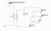
I am adding more and more electronics to my car and am starting to see the need for an another way to hook them up. Currently I have a dashcam (that stays on after the car turns off), Laser Jammers, a Radar Detector, and I may be adding a few more accessories in the future. My first thought was to install a separate fuse box and hook everything in through this but I am somewhat new to car wiring and dont know if there is a better way to do this. Here is a preliminary circuit diagram that shows my concept. What do yall think of this?

I have the BlackvueDR650GW-2CH dashcam with the Power Magic Pro. This device requires an ignition wire, a hot, and a ground wire. I was thinking about using one of the outputs from the fuse box as the ignition wire. For the hot I was going to run a separate wire from from the battery directly to the Power Magic Pro. Should I put a fuse on that wire between the battery and the PMP?

Also do yall have a recommendation on which fuse box I should buy? Are there any good reliable brands?

I appreciate all of the feedback and questions.

Thanks
JM
 

Attachments

  • Screen Shot 2015-10-01 at 4.08.35 PM.png
    Screen Shot 2015-10-01 at 4.08.35 PM.png
    115.9 KB · Views: 2,149
Last edited:
Welcome to ETO, thejm!

It would help to know the year, brand and model of your car so we can look at the electrical schematic for the car (if it can be found).

In the mean time, have you considered the power draw on the battery that these items will require with the charging system off?

Your schematic has the positive lead from the battery going directly to the new accessories from the battery and (by way of the relay) from the new fuse box. Did you mean for that to be the case?

The relay is also directly powered from the lighter fuse and would appear to be powered at all times. Not at all sure why the relay is being used.

I think I understand what you wish to accomplish, but it would be helpful to know a bit more about your experience(s) with automotive wiring and power systems.
 
cowboybob, thank you for your response! I have a 2011 Infiniti g37.

My schematic was probably confusing so ill try to put it into words lol. I essentially want to take a positive lead from the battery, run it through a relay and into a new fuse box. The relay will be triggered via an ignition wire. I was planning on using an add a circuit connected to the cigarette lighter fuse to trigger the relay for lack of a better ignition source.

*It should be noted that the cigarette lighter circuit shuts off when the car is off so it is am ignition controlled circuit.

The 87 lead would go from the relay to the new fuse box. All accessories would then be connected appropriately to the new fuse box. All accessories would be grounded appropriately.

The dashcam is controlled by the Power Magic Pro this has a voltage sensor and a timer that shuts the camera off when the battery drops below a certain voltage to avoid the battery dying and the car not starting. The PMP requires an ignition wire (from the new fuse box), a ground, and a constant power wire (which i was planning on running directly from the battery).

I am an engineer by schooling so I understand the basics (and a few complexities) of circuits and electricity but I am relatively new to automotive wiring. I am getting more and more interested in this topic and am eager to learn from those who know more than me. So, with that said, dont be afraid to tell me what needs to be changed or added to my concept. I am eager to hear your feedback!
 
Last edited:
Since electrical fires are the most common after market, user installed considerations, the single biggest issue with automotive wiring is that ALL circuits (with the sole exception being the main power to the starter) be appropriately fused.

That said, the 2nd issue is appropriate wire sizing and connection/splicing techniques. Always attempt to follow the existing routing bundles (zip tying your new wiring to same if at all possible).

The "accessory power" plug(s), disguised as cigarette lighter(s), is/are a safe source(s) for add-on devices, so long as the above issues are adhered to.

Solder and thoroughly insulate ALL connections where possible.

Example schematic (by no means the only option). Safety and execution are your responsibility! Disconnect Negative Terminal from battery prior to final connections being made to the battery positive terminal!! Take all necessary precautions spelled out in your Owners Manual concerning disconnecting the negative battery terminal.

upload_2015-10-10_10-16-10.png
 
cowboybob,

Thank you again for your reply.

Because my power demands amy change over time, I want to build this circuit and fuse box to handle a 40 amp draw so that I never have to worry about pulling too much power from this and overloading the wires, fuse box, relay, etc (though I dont plan on coming close to exceeding the 40 amps).

If I'm understanding your diagram correctly, I believe it is suggesting drawing power from the accessory/cigarette lighter circuit. This circuit has a 15 amp fuse in it currently and dont think its built to handle a 40 amp draw. Sorry, I probably should told you up front that I want it to handle a 40 amp draw.

I am using a wire sizing chart and sizing my wires appropriately. I would rather overspec something than underspec it and risk a fire or something. I also plan on running the main wire that runs directly form the battery through the existing grommet (or very close to it).
 
Last edited:
OK.

The stock alternator (140A) should handle your additional load level.

I'd use 10AWG, stranded (not solid core) which is good for 12VDC up to 40A with a 3% line loss, at 1M in length.

Under hood space is limited, especially around the battery. Wherever you put the extra fuse box, etc., be sure to secure it well to avoid vibration. I'd put the relay inside that box as well (also secured). I'd still put the 40A fuse and its holder as close to the battery as possible.

And again, however you terminate your wires (screw-ons, bayonet, socket, other types of push-ons or direct connections), be sure to solder those connections to the wire(s). Very small contact resistances can play havoc with maintaining proper voltage levels and, as a result, proper power transfer and the introduction of connection hot spots.


Thank you and will do!
 
Status
Not open for further replies.

New Articles From Microcontroller Tips

Back
Top