Hi, M and T,
It's easy to get confused with this, as there are lots of small changes along the way, so I'm reluctant to go back to earlier CODE examples.
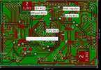
Having said that I did try the 'old' PCB8
https://www.electro-tech-online.com...c-oshonsoft-basic.163337/page-26#post-1433722, which is before PCB9 that has the 'shift register' on.
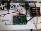
The only times, I get smooth SERVO running is with 2x of my box of SERVOs, while all of the rest jitter.
The latest CODE on the latest PCB9 gives the same results (2x smooth SERVOS), so I think we ought to go from here.
If I put a brake (shock absorb) on the jittering SERVOs, they move smoothly, but in steps, that I think is causing a kind of backlash?
Here is the latest CODE (I'm a bit lost what changes have been made):
The <<<<<<<<<<<<<, point to changes, but I now can't remember what they were?
Code:
'18F4431 32MHz XTL PCB9 REMOTE_SLAVE GPS_UART 040423 1700
Define CONFIG1L = 0x00
Define CONFIG1H = 0x06 '8mHz XTL x4 =32mHz
Define CONFIG2L = 0x0c
Define CONFIG2H = 0x20
Define CONFIG3L = 0x04
Define CONFIG3H = 0x80
Define CONFIG4L = 0x80 'Set for HVP
Define CONFIG4H = 0x00
Define CONFIG5L = 0x0f
Define CONFIG5H = 0xc0
Define CONFIG6L = 0x0f
Define CONFIG6H = 0xe0
Define CONFIG7L = 0x0f
Define CONFIG7H = 0x40
Define CLOCK_FREQUENCY = 32
Define SINGLE_DECIMAL_PLACES = 2
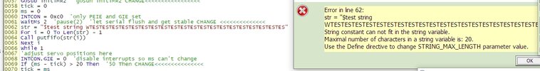
Define STRING_MAX_LENGTH = 20
'Define SIMULATION_WAITMS_VALUE = 1 'Comment in for SIM out for PIC
Dim wordTemp As Word
Dim ServoCount As Byte
Dim i As Word
Dim ServoPos(8) As Word
Dim servoDir(8) As Byte
Dim frame As Word
Dim Buff(80) As Byte
Dim strCount As Byte
Dim rec As Byte
Dim isDone As Bit
Symbol rled = PORTD.7
OSCCON = %01110000 '& h70
TRISA = %11000000 '7=OSC, 6=OSC,
TRISC = %11110010 '6=1-slave4431_cs, 3=74HC164 MR, 2=74HC164 CLK, 0=74HC164 DATA'<<<<<<<<<<<<
TRISD = %00000000
LATC.0 = 0 'ensure data is low
LATC.2 = 0 'and clock
LATC.3 = 1 'Master reset HIGH for run.'<<<<<<<<<<<<<<
'Start up led
rled = 1
WaitMs 1000
rled = 0
WaitMs 1000
rled = 1
WaitMs 1000
rled = 0
WaitMs 1000
For i = 0 To 7
LATC.2 = 1 'send positive clock edge
ServoPos(i) = i * 250 + 2000 '1ms(2000) to 1.875(1 7/8ths - 3750)ms in 1/8th mS steps
LATC.2 = 0 'send negative edge
servoDir(i) = i And 1 '<<<<<<<added
Next i
'TRISC = %11111010 'CCP0 (RC2) & RC0 output'<<<<<<<<<<<<<<<<<<<<
ServoCount = 8 'cause it to reset
T1CON = %00100000 'prescaler = 4
T1CON.0 = 1 'start timer
CCP1CON = %1000 'will go high on interrupt - will start a 0.5mS pulse
frame = 1000 'start everything in 4000 cycles
strCount = 0
isDone = 0
'setup USART for 9600 baud receive
RCSTA = %10010000
TXSTA.BRGH = 1
BAUDCON.BRG16 = 1
SPBRG = 207
PIR1.RCIF = 0
PIE1.RCIE = 1
PIE1.CCP1IE = 1
INTCON.PEIE = 1
INTCON.GIE = 1
While 1
While ServoCount = 0 'wait for 20mS to pass (=1/50th of a second)
Wend
While ServoCount <> 0
Wend
For i = 0 To 7
INTCON.GIE = 0
If servoDir(i) = 1 Then
ServoPos(i) = ServoPos(i) + 40 'add 1/50th to the servo position
Else
ServoPos(i) = ServoPos(i) - 40 'subtract it
Endif
If ServoPos < 2000 Then 'have we gone past the end?
ServoPos(i) = 2000 'yes so make it the end stop
servoDir(i) = 1 'and turn it around
Endif
If ServoPos(i) > 4000 Then 'same for other end
ServoPos(i) = 4000
servoDir(i) = 0
Endif
INTCON.GIE = 1
Next i
'adjust servo positions here
Wend
End
On High Interrupt 'go via location 0x0008
Save System
If PIR1.CCP1IF Then 'has CCP1 triggered?
wordTemp.HB = CCPR1H 'get value of CCPR1 into wordTemp
wordTemp.LB = CCPR1L
If CCP1CON = 0x08 Then 'have we started the 1000 cycle pulse
CCP1CON = 0x09 'yes so end the pulse after 0.5mS
wordTemp = wordTemp + 1000 'adding 1000 will make pulse 0.5mS long
Else
LATC.0 = 0 'clear the data pin
CCP1CON = 0x08 'No so output the timed gap
If ServoCount < 8 Then
'still doing the servos so add remainder of time
wordTemp = wordTemp + ServoPos(ServoCount)
wordTemp = wordTemp - 1000 'knock of the 1000 (0.5mS) already elapsed
frame = frame - ServoPos(ServoCount)
ServoCount = ServoCount + 1
Else
'done all the servos so just the frame gap to do
wordTemp = wordTemp + frame
frame = 39000 '40,000(20mS) minus time of positive pulse(0.5mS)
ServoCount = 0 'start all over again
LATC.0 = 1 'will become first pulse
Endif
Endif
CCPR1H = wordTemp.HB 'put value back into CCPR1
CCPR1L = wordTemp.LB
PIR1.CCP1IF = 0 'clear interrupt flag
Endif
If PIR1.RCIF Then
rec = RCREG 'get the received character
If RCSTA.OERR Or RCSTA.FERR Then 'neither of these should ever occur.
RCSTA.CREN = 0 'this is kinda wishful thinking
If PIR1.RCIF Then
rec = RCREG
Endif
RCSTA.CREN = 1 'as any data received is corrupt
strCount = 0 'however, reset everything
isDone = 0 'and hope for the best
Else 'no errors so use the data
If strCount = 0 And isDone = 0 Then 'are we already receiving
'waiting for $ 'no so wait
If rec = "$" Then 'for $ to appear'<<<<<<<<<<<<<<<<<<<<<<<<
Buff(strCount) = rec 'start receiving
strCount = strCount + 1
Endif
Else
If isDone = 0 And strCount < 79 Then 'have we collected a full string?
Buff(strCount) = rec 'no so carry on storing
strCount = strCount + 1
If rec = "W" Then 'have we got the "endOfString" character'<<<<<<<<<<<<
isDone = 1 'yes, so set done true
'put break here
Endif
Else
If isDone = 0 Then '?????????<<<<<<<<<<<<<<<<<<<<<<<
'still waiting to start or buffer overflow
strCount = 0
Endif
Endif
Endif '<<<<<<<<<<<<<<<
Endif
Endif 'end RS232 if
Resume
The oscilloscope readings I posted, kind of confuse me! I can see the on off times changing but as the screen is narrow, I don't see the full picture.
To me the FRAME looks like it's longer than the recommended 20ms. (I think I recall that this doesn't matter, but perhaps it should be 20ms for testing)
Tomorrow, I'll try some digital analyser tests, which log the output numbers, which may make things clearer?
Note: I haven't considered #211 yet!
EDIT: T, I had a quick look at the latest CODE, and
[ If servoPos(i) < 2000 Then 'have we gone past ] applies here too. Let's see what M thinks.
Regarding SAVE SYSTEM, this saves the system when returning from and INTERRUPT, so it carries on correctly.
C

")
