Continue to Site

Welcome to our site!

Electro Tech is an online community (with over 170,000 members) who enjoy talking about and building electronic circuits, projects and gadgets. To participate you need to register. Registration is free. Click here to register now.

  • Welcome to our site! Electro Tech is an online community (with over 170,000 members) who enjoy talking about and building electronic circuits, projects and gadgets. To participate you need to register. Registration is free. Click here to register now.

ADC with 16f877

Status
Not open for further replies.

raviram87

New Member
hello people....

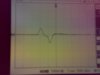
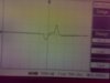
as part of my eye movement project, i rigged up a circuit thats working well and gave me the two outputs (images 1 and 2 attched below) when i look right and left... note that when i look straight i got a 0 output...

to differentiate between the two movements, next i wish to convert these results into digital for which i want to use a PIC16f877 uC... however i learnt that the PIC wont accept negative analog inputs...

can u offer suggestions on how i can achieve this A to D Conversion???
 

Attachments

  • Image1.jpg
    Image1.jpg
    323.6 KB · Views: 506
  • Image2.jpg
    Image2.jpg
    347.8 KB · Views: 324
You can use a separate A2D converter or you can offset the voltage so that 0V input becomes 2.5V at the analog input of the PIC.

If you are only interested about the changes in signal, you can use a couple of resistors to centre the voltage of the analog input at 2.5V, and then a big capacitor to couple the signal to the analog input.
 
is it like tha PIC cant accept -ve analog inputs at all????

and if i introduce say a summing amplifier and shift both signals so that they are entirely positive, will the digitisation then yield different results????

i.e., now the signals at image1 and image2 will have no negative half... the signal will be shifed above the 0 line... and i then digitise....

will i get different codes for the 2 signals then so that i build a decision program such that if i get say code A, then its right move and if i get code B then its a left movement....
 
thanks for the help.... can u also guide me on the other question i asked???

abt the digitisation after removing the negative parts of the analog input... am i assured to get different digital output for the two signals i have shown?
 
You get a digital value from 0 to 1023, it's up to you how you use it, but in the scheme I mentioned above 512 will be the 'zero' point, and less than that will be negative.
 
i understand that two pins of the PIC 16f877 are designated as Vref(low) and Vref(high) for the ADC module of the PIC....

why are they used for?? by applying say Vref(high) as 5V and Vref(low) as -5V, can the PIC accept negative cycles of incoming analog signal and convert them to digital?
 
raviram87 said:
i understand that two pins of the PIC 16f877 are designated as Vref(low) and Vref(high) for the ADC module of the PIC....

why are they used for?? by applying say Vref(high) as 5V and Vref(low) as -5V, can the PIC accept negative cycles of incoming analog signal and convert them to digital?

I've already told you can't input negative voltages, and you might try reading the datasheet about the Vref pins - which explains their range.
 
Status
Not open for further replies.

Latest threads

New Articles From Microcontroller Tips

Back
Top