Hi,
I built a PCB using a PIC to do PWM motor control on the fuel pump motor in a car. This is working despite the PCB ground being noisy as Motor - is being switched on and off.
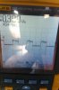
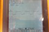
I'm trying to sample a 0-5V analog input from a car sensor and feed that into an ADC pin on the PIC. The problem is that the Car GND and PCB ground are different as shown in the pictures below. The voltage of the signal with respect to car ground is fine, but the voltage of the signal with respect to PCB ground has the problems. This is apparent from the voltage waveform of PCB ground with respect to car GND.
I tried using inductors / chokes. I tried Capacitors from signal to GND but I am having problems because the signal current is so weak, but I have a feeling that it needs some sort of decoupling between the signal to gnd or between the car ground and PCB ground.
Any suggestions?
Thanks.
I built a PCB using a PIC to do PWM motor control on the fuel pump motor in a car. This is working despite the PCB ground being noisy as Motor - is being switched on and off.
I'm trying to sample a 0-5V analog input from a car sensor and feed that into an ADC pin on the PIC. The problem is that the Car GND and PCB ground are different as shown in the pictures below. The voltage of the signal with respect to car ground is fine, but the voltage of the signal with respect to PCB ground has the problems. This is apparent from the voltage waveform of PCB ground with respect to car GND.
I tried using inductors / chokes. I tried Capacitors from signal to GND but I am having problems because the signal current is so weak, but I have a feeling that it needs some sort of decoupling between the signal to gnd or between the car ground and PCB ground.
Any suggestions?
Thanks.