Electro Tech is an online community (with over 170,000 members) who enjoy talking about and building electronic circuits, projects and gadgets. To participate you need to register. Registration is free. Click here to register now.
Welcome to our site! Electro Tech is an online community (with over 170,000 members) who enjoy talking about and building electronic circuits, projects and gadgets. To participate you need to register. Registration is free. Click here to register now.
listen guys ive been working so much im lost here. is it possible someone can give me a 5v sample? Like draw it out for me. I think Radio Shack is making me stupid heh
You just need a simple two resistor attenuator, fairly low values if you're not using an opamp.
Assuming you're using the 5V Vdd for the reference?, you need 5V across the bottom resistor, and 5.023V across the top one - so if you make the bottom resistor 4.7K, and the top one 4.7K with a 470 ohm preset in series, you can adjust the preset to make it read exactly right.
AtomSoft, I'm rather confused about your Vdd and Vref requirements.
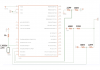
I thought that you're planning to use a PIC18LF1320 powered by Vdd=3.3V, aren't you? Look to the attached schematic.
No, you adjust each one to read the same voltage, 10.23V FSD on all inputs.
Easiest way is to set your program to display the value of the ADC (0-1023), and add a decimal point between the 10 and the 23 in the software - again, check my tutorial which does exactly this. Then connect a battery (say 9V) to each input in turn, and connect your multimeter across the battery (on its 19.99V range) - adjust the preset on each input so it reads exactly the same as your multimeter.
Nigel the issue is do i need a 10.23v source? if not how the heck am i going to get it to read 10.23v on each.
Unless you mean if i put a 9v battery on it it should read out 0900 as the value when i adjust the resistor. Since im cutting the voltage in half it will be 4.5v so i can use the resistor to bring it higher am i correct?
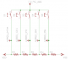
Ok this is about ADC but easier project. I have a 5v supply and i can get adc value of some resistors but im scared if the vdd/vss drops a little then my whole project is done for since the values wont match and buttons will have no use.
Im using about 5x1k resistors to create the different values now how would i calculate the value based on vdd/vss ?
like im using a stable 5v supply right now (pickit 2 power) here are my results:
The ADRES result is in image and the actual resistors are all 1k each.
How do i calculate the percentage? So i can calculate for voltage drops and such?
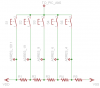
hi atom,
Using the same 5, resistor chain the answer is no.
If you have a spare adc input, at power up, you could sample the +Vsup and adjust the software switch sampling voltage gaps to suit
If you used a fixed 3.3V it would be easy to calculate the voltage drops at the resistor chain, still use say 1K's
EDIT:
Using 1K's at 3.3V would give increments of 0.66V along the chain
i mean since i uuse the VDD/VSS as VREF if i use a 3v supply and get a value of 1023 then when i use a 5v Supply instead of 3v will i still get a 1023 as my vdd for both?
i mean since i uuse the VDD/VSS as VREF if i use a 3v supply and get a value of 1023 then when i use a 5v Supply instead of 3v will i still get a 1023 as my vdd for both?
If I understand you correctly, you are using the PIC supply [internal ref] for the adc.
If you run from 5V or 3.3V you will still get 1023 for a 10bit adc.
ok cool. Thats for project 2 i have it working nicely. Its a little Clock via LCD and 5 buttons on 1 pin. Going to show it when i goto a school interview.
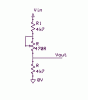
Just a note, you can increase your voltage safety margin (and decrease partscount) by removing R5. So one end switch goes to 5v and the other goes to 0v. Then you have the max voltage possible from each stage.
And I guess you know this, but if you use Vdd as the ADC reference, for examples like the one above the ADC reference voltage scales linearly with battery voltage etc, so you don't need to be worried about "battery voltage drops a little and buttons wont work".
This site uses cookies to help personalise content, tailor your experience and to keep you logged in if you register.
By continuing to use this site, you are consenting to our use of cookies.

 is it possible someone can give me a 5v sample? Like draw it out for me. I think Radio Shack is making me stupid heh