Continue to Site

Welcome to our site!

Electro Tech is an online community (with over 170,000 members) who enjoy talking about and building electronic circuits, projects and gadgets. To participate you need to register. Registration is free. Click here to register now.

  • Welcome to our site! Electro Tech is an online community (with over 170,000 members) who enjoy talking about and building electronic circuits, projects and gadgets. To participate you need to register. Registration is free. Click here to register now.

Active filter design

Status
Not open for further replies.
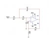
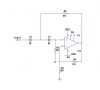
I have been working on some active filters for my VU meters. I used the equation and the circuits form the 2005 ARRL handbook, but I'm not sure if they're working.

I was using a 741 for the low pass, then I tried using a TL082 for both the high pass and the low pass. I think my problem is that I didn't calculate properly, the only value that I think that I might need is the dB for the 2 filters.

How do I find the dB of the filter and what is it?

Is it the rejection of the filter, Is it the tolerance of the filter?

Any help would be appreciated.
 
Either post the specs for your filters, and I will show you how to use FilterPro (free download) to design them, or post your circuit(s), and I will show you how to use LTSpice to plot the response.
 
.

How do I find the dB of the filter and what is it?

Is it the rejection of the filter, Is it the tolerance of the filter?
dB is a decibel which is a logarithmic representation of the power gain ratio or power loss ratio of any circuit (in this case a filter). It is equal to 10*Log (Po/Pi) or 20*log(Vo/Vi) where Po and Vo are the output power or voltage values and Pi and Vi are the input power or voltage values.

Strictly speaking you can only use the voltage version of the formula if the input and output impedances are identical but typically any impedance differences are ignored.

So then in the examples in the handbook, when it says that it has a f = -3dB, they are talking about the filter having a 3dB loss between the input and output.

I connected a series RC network to the input of the buffer amp for the VU meter, and it's acting like a filter in itself. But since this problem is likely to come up in the future, I'll post my schematic and calculations as soon as I finish the schematic.
 
So then in the examples in the handbook, when it says that it has a f = -3dB, they are talking about the filter having a 3dB loss between the input and output.
The is another interpretation I should mention, and that is the dB ratio for different frequencies. Thus the -3dB point of a filter is the frequency at which the gain has dropped 3dB from the midpoint or flat portion of the gain versus frequency. It's typically called the "corner" frequency of the filter rolloff.
 
Okay, I have finished the circuit, and the calculations to go with them.

The circuits are attached, and the calculations are:

Low Pass

α = 1.414 (number of stages = 1)
k = 1
f = 1kHz
ω = 6283.2 (2 x pi x f)
C1 = ≤ 5nF (1nF)
C2 = 10nF
R1 = 15.9k (15k)
R2 = 169k (150k)
R3 = 0
R4 = 0

Low Pass 2

α = 1.414
k = 2
f = 1kHz
ω = 6283.2
C1 ≤ 15nF (10nF)
C2 = 10nF
R1 = 10k
R2 = 27k
R3 = 75k
R4 = 75k

High Pass

α = 1.414
k = 1
f = 1kHz
ω = 6283.2
C1, C2 = 10nF
R1 = 22k
R2 = 11.5k (10k)
R3 = 0
R4 = 0

But from what crutschow said, then the f should actually be the drop off rate of the filter, which would explain why my filters are doing such a poor job of "filtering".

Circuit 1 is the low pass, and circuit 2 is the high pass.

Thanks for your help.
Vince
 

Attachments

  • low pass.JPG
    low pass.JPG
    16 KB · Views: 592
  • high pass.JPG
    high pass.JPG
    16 KB · Views: 834
Last edited:
Okay,
But from what crutschow said, then the f should actually be the drop off rate of the filter, which would explain why my filters are doing such a poor job of "filtering".
f is the point at which the filter has rolled off -3dB (the corner frequency).

The drop off rate (in dB/octave or dB/decade of frequency change) is determined by the order of the filter. The second-order filter you have designed would have a drop off rate of 12dB/octave or 40dB/decade.

R3 and R4 are equal to infinity (no resistor) not 0 (a short).

What do you mean "a poor job of filtering"?

P.S. Have you used the free program FILTERPRO from TI? It greatly simplifies the design of active filters.
 
FilterPro selects weird resistor and capacitor values.
A Sallen and Key second order Butterworth filter can have a gain of 1 and the resistors or capacitors have one simply double value of the other.
Or, the resistors can be the same and the capacitors can be the same and a Butterworth response is when the opamp has a gain of about 1.6.
 
What do you mean "a poor job of filtering"?

I would set the filter to a cut off frequency of 1kHz but it wouldn't actually cut off at that frequency, in fact it would continue to allow frequencies to pass until they were no longer audible. This happened in multisim and on my bread board.
 
No real filter has the "brick-wall" cut-off characteristics of an ideal filter. The filters you show have a roll-off of 12-dB/octave. Is that what you observed?

If you desire a faster roll-off then you need to build a higher-order filter.
 
Status
Not open for further replies.

Latest threads

Back
Top