Continue to Site

Welcome to our site!

Electro Tech is an online community (with over 170,000 members) who enjoy talking about and building electronic circuits, projects and gadgets. To participate you need to register. Registration is free. Click here to register now.

  • Welcome to our site! Electro Tech is an online community (with over 170,000 members) who enjoy talking about and building electronic circuits, projects and gadgets. To participate you need to register. Registration is free. Click here to register now.

Activating a charging circuit by a microcontroller

Status
Not open for further replies.
Hi All,

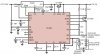
I'm currently in a situation that I would like to activate or let the charging circuit work. I will use the attached circuit.
what I thought about is just use the GND pin of the ground circuit and connect it with a switching transistor, so that when I want to activate it, just pull the transistor to ground and give the charging circuit a ground through the microcontroller, is this a working approach or there is better?
 

Attachments

  • LTC4000-three-LiFePO4-cells-charger.jpg
    LTC4000-three-LiFePO4-cells-charger.jpg
    65.1 KB · Views: 193
The LTC4000 has an "Enable Charging" -pin:

"ENC (Pin 5/Pin 1): Enable Charging Pin. High impedance
digital input pin. Pull this pin above 1.5V to enable charging
and below 0.5V to disable charging. Leaving this pin
open causes the internal 2μA pull-up current to pull the
pin to 2.5V (typical)."
 
Thanks for your reply.
I have found a better and cost effective soultion, which is here https://www.electro-tech-online.com/custompdfs/2013/01/01276a.pdf
they say in that datasheet if you want to control the charging, you can put a high impedance on the pin PROG, what does this mean ? is it controlable by a uC ?

Pin PROG is for controlling the charge current level by means of a resistor (listed in Table 4) and explained under Fast Charge Current Set (PROG).

It would be unnecessarily complicated to use a uC to control the value of that resistor.
 
As the output of microcontrollers can go very near 0V, you could just attach multiple resistors form the prog pin to IO's. And turning the IO's from an intput (high impedance) to an output set to 0. If you wanted to control the charge current, two in parallel, or three could be used, but ultimately you would just need one IO for charging, or not charging.

Note: those microchip charger chips are great, but do have a limited charge current capability. If you're charging batteries over 1200mAH, it may take a while, as they will limit current based on the temperature of the chip (with sot23-5, that is around 260mA).
 
You should be able to connect pin 10 via the charge-current-control resistor and the collector-emitter path of an NPN transistor to ground. The micro can then control (via a base resistor) the switching on/off of the transistor. When the transistor is off pin 10 sees the high impedance referred to in the datasheet, so charging is disabled.
 
I should have read the OP's post title a little more carefully...:eek:.
 
Ehh it happens, but if the OP was to look at the datasheet for those microchip devices - it actually has example schematics of turning on/off charging using the PROG pin :)
 
Status
Not open for further replies.

Latest threads

New Articles From Microcontroller Tips

Back
Top