Continue to Site

Welcome to our site!

Electro Tech is an online community (with over 170,000 members) who enjoy talking about and building electronic circuits, projects and gadgets. To participate you need to register. Registration is free. Click here to register now.

  • Welcome to our site! Electro Tech is an online community (with over 170,000 members) who enjoy talking about and building electronic circuits, projects and gadgets. To participate you need to register. Registration is free. Click here to register now.

AC voltage split by relay

Status
Not open for further replies.
Hello there!

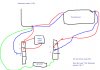
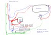
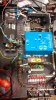
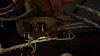
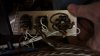
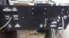
This is a plea for help. I am trying to get an old film scanner working. It has 110v fed into a central junction. The current goes through a relay and when it comes back to a separate junction, there is no voltage between live and neutral. The brown is live with 55v when multimeter is placed on live and the earth of the metal casing.

None know why the voltage splits/drops?

Many thanks,

Patrick
 
Your description of you problem is not clear. Post a schematic showing the wiring between the mains plug and the point where you have the problem. As you give your location as the UK your mains voltage will be 240 volts. I would expect you to get a reading of 240 volts between live and the casing. This is assuming the casing is earthed. Earth and neutral should be nominally the same potential as they are connected together at som point in the distribution system. What do you mean by "a central junction" ?

Les.
 
Hi Les,

Thanks for your reply. I'm in the UK but using American voltage so the mains is thread through a transformer, which reduces it to 110V. The central junction the mains goes to is a rack, see photo

In the diagram, there is 55 v across 3 & 4 (across live and neutral). But there is 55 volts just in the live at 2.

What I need is 110v across 2 (live) and 5 neutral to power other bits in the scanner such as PSU, control panel etc..

Any help would be very much appreciated,

Thanks,

Patrick
 

Attachments

  • circuit2.jpg
    circuit2.jpg
    174.2 KB · Views: 129
  • IMG_20171204_140838779 copy.jpg
    IMG_20171204_140838779 copy.jpg
    1 MB · Views: 117
Last edited:
Are you using a yellow building site transformer? If so then you should be aware that the 110V output is centre tapped to earth, so live and neutral from the transformer will both read 55V to earth. Measuring directly between 2 and 5, though, you should always see 110V when the relay is closed (on).

Another thing to be aware of is that digital multimeters have a very high input resistance - they can pick up noise if not connected to anything, which can give you false readings. So if the relay is not closing, point 2 might be "floating" and - while you might measure 55V with only the meter connected- it will disappear as soon as you connect a load.

I assume you can hear the relay clicking so you know it's coming on?
 
Many thanks Tom, It's truly baffling.

I am not using a yellow building site transformer, but one that came with the scanner. But it reads live and neutral to earth, both 55V just as you say.

Thank you for alerting me to problems with the relay. There are 4 of them and I hear no clicking. Maybe they all need replacement?

Do you know about the life span of relays? Do they need frequent replacement?
 
I think tomizett has explained the 55 volt reading. I am assuming that your "relay splits voltage" box is a set of normally open contacts on the relay. What controls the power to the relay coil ? You say there are four relays. Can you draw a block diagram of the complete setup ? (You attempt at drawing a schematic was not very good. It makes it look like live, neutral and earth are all shorted together at the end of the black wire.) Are terminals 3 & 4 the incomming 240 volt mains ? If so your comment "2 & 3 are live wires 55 V" is confusing as I would expect 3 to be at 240 volts with respect to earth (And neutral) Have you checked that you read 110 volts BETWEEN 1 & 5 ?

Les.
 
Last edited:
Yes, there's 110v between 1 and 5. I've tried to sketch a more informative diagram. Sorry about the poor graphics!

Terminals 3 and 4 are the output of the transformer which is split to 55v across live and neutral. In put to the transformer is 110v
 

Attachments

  • circuit2.jpg
    circuit2.jpg
    192.5 KB · Views: 120
I am totally confused. You seem to have 110 volts on the primary and secondary of the transformer. Where does the 240 volt mains come into the circuit ? Can you draw the relays properly showing the coil and contacts. The simplest relay would have at least 4 connections 2 for the coil and 2 for a single set of contacts.

Les.
 
Many thanks, Les, for the info about the relays. I'll do a more detailed drawing tomorrow including the relays.

The 240 V goes to a transformer outside the scanner which provides 110 V output. This output goes to a transformer inside the scanner which halves the voltage to 55V across two points 3 & 4.

The 110 Volts also goes to a rack of connections inside the scanner with the relays. The live wire comes off the rack goes through the first relay, where it halves to 55v.
 
I got the impression from your posts that the transformer in your diagram was the 240 to 110 volt transformer. Is the item labled "transformer" in your diagram just a transformer or is it a power supply with DC output. Also is the red wire from the "transformer" connected to ground at teminal 3 ? In the last sentence of post #9 you imply that a relay halves the 110 volts down to 55 volts. A relay cannot do this. A relay is just like a switch (Or group of switches) that are operated by passing current through an electro magnet (The relay coil) The contacts are the switch part. As you give your specialisation as power electronics you may be more familiar with the term contactor. Contactors and relays are basically the same thing. If you have a schematic of the scanner can you post it so we can see the big picture

Les.
 
None know why the voltage splits/drops?


I know how it happens. But what's actually happening in your case, I don't have enough info.

The easiest way to get 55 V is through leakage paths in a line filter. See https://www.farnell.com/datasheets/1576569.pdf Seethe two capacitors on the load side? If that ground is broken, you'll get 55 V or so. It's from similar leakages in the two capacitors. It can only support a few mA.
 
Hi Les,

Sorry, I have no idea what the "transformer" is because many of the components are unlabelled. I thought it might be a transformer because of how it looked (see photos). However, the multimeter reads AC.

The scanner was a joint product made by Quantel (Domino) and Oxberry in the mid nineties. The firm that took on Quantel have no archive of circuit diagrams, to my knowledge, however, I need to produce a diagram simply from what I see.

KeepItSimpleStupid (like the name!) I could replace the capacitors, should I do this.

I log into this forum this morning, with a conundrum. It's amazing what you learn in day! Thnx
 

Attachments

  • "transformer".jpg
    "transformer".jpg
    217.5 KB · Views: 107
  • interior.jpg
    interior.jpg
    767.9 KB · Views: 107
Things are now beginning to make sense. When I thought the transformer that you were referring to was the external 240 to 110 volt transformer I could not see how it was possible for the relay to pull in as appeared to be controlling the 240 volts input to what I thought was the external transformer. So there would be no way the relay coil could be powered. We can now discount the external transformer as being anything to do with the problem. As the internal transformer is powered on as soon as 110 volts AC is supplied to the scanner it must provide the supply that drives the relay coil so that it's NO contact can make the connection between terminals 1 & 2. Is there only one secondary winding on the internal transformer ? The reason behind this question is that it is likely that the transformer will provide a DC supply to some control circuit via a rectifier. If there is only one secondary and one side is earthed then only half wave recification could be used to provide the DC as it would be normal for one side of the DC supply to be grounded. (Probably the negative.) My guess would be that the realy whose contacts connect to terminals 1 & 2 is part of some interlock circuit that check that covers are closed and / or that some of the power supply voltages are within specification. Are the relay coils AC or DC rated ? If they are AC then the interlock circuit will probably only be looking at micro swiches being operated by covers. Can you provide some pictures of the scanner so we can see what kind of interlocks for safety. The only type of film scanner I have seen is a Minolta "Dimage scan dual". (This just scans 6 frames of 35mm film at a time so it is only small and dose not present any safety hazzard.)

Les.
 
I'm not sure about 2 outputs on the internal transformer, but a bit of a revelation today, Les. I measured the output from the internal transformer across the points 3 & 4 with the multimeter on DC and it read 24v.

The relay coils: 1st is 24v dc coil with 250v switch, 2nd, 3rd and 4th are 12v dc with 250v switches.

Here are some more photos of the underneath of the relays, and a new circuit diagram, hopefully clearer!


Many thanks for your insights
 

Attachments

  • circuit.pdf
    495.1 KB · Views: 123
  • underneath.jpg
    underneath.jpg
    327.7 KB · Views: 104
  • IMG_20171208_100243388.jpg
    IMG_20171208_100243388.jpg
    365 KB · Views: 107
  • backplate.jpg
    backplate.jpg
    572.4 KB · Views: 104
Looking at the pictures in post #12 the item that you call a transformer is definitely a transformer so it's output can only be AC. I assume the white wires twisted together on the left two connections are one winding and the black wires on the right two terminals are another winding. Are you sure that one pair go to terminals 1 & 5 on the left hand terminal block and the other pair go to terminals 3 & 4 on your sketch in post #7 ? Your pictures do not give me any fealing for the scale of the device and what safety interlocks it might have. Does it scan normal size film (35mm , the old 120 2.25" wide format or some very large format) Can you give me some idea of what are of power electronics you specialize in ? The highest power I have worked on is a 300 amp 440 volt three phase to a factory. So I don't have a feeling for what someone working on megawatt systems would be expected to know.

Les.
 
Thanks, Les. I am away from my workshop until Monday, but I'm pretty sure the input to the transformer is from terminals 1 and 5, and I have tested the white wires on the left and they definitely lead to points 3 & 4 through small white wires. I have two readings across 3 & 4 - 55V when the multimeter is set to AC and 24V when the multimeter is set to DC.

The backplate shown is about 30 x 70 cms. This safety cutout mechanism may be to do with a port on the back called Temp Cutout. The first 24Volt DC relay has white wires leading to this terminal, ( the multimeter reads 24V dc across it). I need to look at all the components that plug into these ports, and see if I can locate this TempCutout component.

The scanner is for 16mm and 35mm film. Quantel were most famous for Paintbox, a software that preceded Photoshop. However, they also made advanced scanning equipment for the film industry. The motors and optics ofmy scanner were made by Oxberry, a company in New Jersey famous for their engineering. It scans slowly so I guess it can not be too higher wattage. Anyway hope I can get it working! I'll check the transformer again on Monday.

Once again, Les, many thanks for your help and input.
 
Before spending too much time getting the hardware working have you considered the software required to comunicate with the scanner ?

Les.
 
The first 24Volt DC relay has white wires leading to this terminal, ( the multimeter reads 24V dc across it).
This could be a teller... It sounds to me like this is a connector for a normally-closed external cutout that will open the relay in the event of a fault. The 24V you're seeing at the socket is available to switch on the relay, but is not reaching it because the cutout is missing.
If you can trace a circuit from the +24V supply, through the "Temp Cutout" connector, then through the relay coil, and then back to 0V on the supply - then maybe all you need to do is short the wires at the connector.
You'd need to be very sure that the connector is actually in series with the relay coil, though, because if you just end up shorting the supply you might well damage it.
 
Status
Not open for further replies.

Latest threads

New Articles From Microcontroller Tips

Back
Top