Hi everyone,I'm new here and this is my first thread.
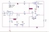
I'm recently undertaking a laser ranging project,using phase-shift measurement.I was trying to directly modulate the laser beam of a laser diode using a sinusoidal wave with frequency around 10MHz and then build a receiving circuit to convert this modulated beam into an electric signal.I have already built an emitting circuit here,injecting a bias current together with a modulated current into the diode.I'm always trying to make the circuit as simple as possible so as to reduce mistakes,since i don't have a good circuit design sense.As for the receiving part,my basic idea is to use a PIN photodiode followed by a pre-ampifier but i find it hard to capture the modulated signal.I don't know what's wrong here,but the desired signal just won't come out.Could you give me some advice on that?Thx
I'm recently undertaking a laser ranging project,using phase-shift measurement.I was trying to directly modulate the laser beam of a laser diode using a sinusoidal wave with frequency around 10MHz and then build a receiving circuit to convert this modulated beam into an electric signal.I have already built an emitting circuit here,injecting a bias current together with a modulated current into the diode.I'm always trying to make the circuit as simple as possible so as to reduce mistakes,since i don't have a good circuit design sense.As for the receiving part,my basic idea is to use a PIN photodiode followed by a pre-ampifier but i find it hard to capture the modulated signal.I don't know what's wrong here,but the desired signal just won't come out.Could you give me some advice on that?Thx
")