https://www.skuttle.com/pdfs/a50_install.pdf
OK it's not repaired, but I now know what's inside. This is a control that senses the AC current when a motor turns on. One wire of the motor is threaded through a metal U-bracket in the end of the case. The black and white wires, then act as a switch for an external 24VAC control circuit. Mine was always switched-on. When I open the case I thought great!...all the components are standard off the shelf parts. I traced out the circuit and drew up a schematic. Bench tested it and everything worked...except the one custom part...the sense coil. It was open. Anyway, I thought someone else might interested in the circuit design.
Ken
OK it's not repaired, but I now know what's inside. This is a control that senses the AC current when a motor turns on. One wire of the motor is threaded through a metal U-bracket in the end of the case. The black and white wires, then act as a switch for an external 24VAC control circuit. Mine was always switched-on. When I open the case I thought great!...all the components are standard off the shelf parts. I traced out the circuit and drew up a schematic. Bench tested it and everything worked...except the one custom part...the sense coil. It was open.
Anyway, I thought someone else might interested in the circuit design.Ken
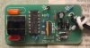
") One loop "primary", through the metal U-shaped strap core. The rest of the core is a screw through the "secondary" coil on the PCB. The square bobbin had a gazillion turns of hair fine wire. Didn't want to spend my time rewinding it...just bought another relay. The schematic was just because I wanted to see how they powered a "closed" active switch in series with the load.
One loop "primary", through the metal U-shaped strap core. The rest of the core is a screw through the "secondary" coil on the PCB. The square bobbin had a gazillion turns of hair fine wire. Didn't want to spend my time rewinding it...just bought another relay. The schematic was just because I wanted to see how they powered a "closed" active switch in series with the load.