Electro Tech is an online community (with over 170,000 members) who enjoy talking about and building electronic circuits, projects and gadgets. To participate you need to register. Registration is free. Click here to register now.
Welcome to our site! Electro Tech is an online community (with over 170,000 members) who enjoy talking about and building electronic circuits, projects and gadgets. To participate you need to register. Registration is free. Click here to register now.
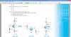
The trick here is to redraw the circuit so the collector get at top. Also you just have to wrap your mind around the idea of using a negative voltage instead of zero.
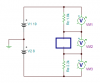
Emitter current means current through Base plus current through Collector, here the Base is directly connected to 0V so that the emitter voltage is -0.6V. But what is the base current so that we can sum the total emitter current?
And voltage difference between base to emitter is 0.6V. But we also get fix voltage from base to collector or emitter to collector? I think not. Lets see.
Voltage across the 2k2 resistor is (8V-0.6)=7.4V so that the current across the resistor is 3.3mA. Can I say it is an emitter current? There's nothing current limitter in base, then how will I assume base current, so that I can calculate total emitter current.
Emitter is -0.6V and base is 0V then how can I guess the collector current? Because I am confuse about the CE voltage drop (like BE drop) to calculate voltage across CE voltage.
The base current is so small that you do not need it in this calculation because the base does not have any resistors to cause a voltage drop. The collector current is the emitter current minus the base current but the base current is almost nothing then the collector current is the same as the emitter current.
You know the collector resistor value, the collector supply voltage and its current then you can simply calculate Vc and Vce.
Emitter is -0.6V and base is 0V then how can I guess the collector current? Because I am confuse about the CE voltage drop (like BE drop) to calculate voltage across CE voltage.
Ok, if there's no base current then the collector current is same as emitter current then:
Voltage across 1k8 is (3.3mA x 1k8)= 5.04V
Vc is (10V-5.04V)= 4.06V
Vce is (4.06V+0.6V)= 4.66V Solved!
Few questions again:
¤ Base is connected directly in a voltage which is 0.6V higher than the emitter, which means there is base current too. But why we ignore here the important base current? Because it is 3.3mA divided by 100 (beta) and it is so small, so?
¤ There's 4.66V difference between Emitter to Collector voltage. Which things determined the CE voltage? Due to 'turn ON resistance' of the transistor? Or are there ani fix voltage drop (like BE has 0.6V fix drop) across Coollector to Emitter?
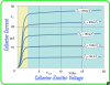
We were not told which transistor. It might be a BC548C with a current gain as high as 800 then the base current is 3.3mA/800= 4.1uA which is very very small. The Vce voltage is determined by the amount the transistor is turned on. It will turn on more if the emitter resistor value is lower causing higher base, emitter and collector currents.
The Vce voltage is determined by the amount the transistor is turned on. It will turn on more if the emitter resistor value is lower causing higher base, emitter and collector currents.
Interesting! This is basic thing but I never got a chance to think about it.
I understood: If the transistor is 'partially' turned ON (less current flow), then the collector to emitter has higher voltage drop. Can't I say "now the transistor has higher turn ON resistance"?
[maybe relay driver (12V) transistor has very less Vce and very less turn ON resistance to drive relay coil.]
The collector to emitter of a partially turned on transistor is not a resistance because when the collector to emitter voltage is increased the current stays the same, it is a constant current source or sink. If it was a resistance and the voltage across it was increased then the current would also increase.
This site uses cookies to help personalise content, tailor your experience and to keep you logged in if you register.
By continuing to use this site, you are consenting to our use of cookies.