Continue to Site

Welcome to our site!

Electro Tech is an online community (with over 170,000 members) who enjoy talking about and building electronic circuits, projects and gadgets. To participate you need to register. Registration is free. Click here to register now.

  • Welcome to our site! Electro Tech is an online community (with over 170,000 members) who enjoy talking about and building electronic circuits, projects and gadgets. To participate you need to register. Registration is free. Click here to register now.

A little understanding

Status
Not open for further replies.

Ian Rogers

User Extraordinaire
Forum Supporter
Most Helpful Member
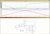
Hi... You all know I'm a software guy... I know enough electronics to do my job but on a recent repair to an older system I had an issue with the current convertor.... Its basically a simple op-amp voltage to current convertor, but with added circiuts.

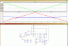
The designer ( The old retired director of my old firm ) seems to have used up a quad op-amp package..

The input voltage is 3 to 4 volts... the output current measures 1.5mA to 2.5mA respectively

My question is what is the purpose of the feedback loops... Is one an over current, this is what it appears to be....

The job in question had fried R4.... instead of 243Ω we measured 6.7K... I'm trying to evaluate the issue so I can find out how it happened.

I hope someone can explain the circuit a bit better.
current convertor.PNG
 
Hi, hmm if R4 was failed high ohms that is not a good sign, it means R4 was exposed to a sustained over-wattage situation (too much current through it). That excess current can only come through the IC via the output drivers in U1A, so it's very likely the IC is toast. I would replace the IC with R4.

Re the operation, there's one basic feedback mechanism; if the voltage drop across R4 is not high enough then the output of U1A is changed in voltage. The reason there are two branches in the feedback loop is because neither end of R4 is at a known fixed voltage, so the feedback measures 2 points to get the voltage between the 2 points, which then produces one feedback signal.

One of the analogue experts can probably explain the operation better than me but that's the basics of it.
 
Cheers Roman... I already swapped out the op-amp as this is what I thought it was.... I think as you do, the chip was damaged aswell.... I think someone had placed 24 volts ( the crane voltage ) on to the top of R4.... The problem has been solved... However this was the reason behind the post.... If that wasn't the case, and the overcurrent detection circuit ( if that is what it is ) has obviously failed to do its job....

The crane sits on a dock in Lancaster and are prey to high powered RF communication, ship to shore! I'm hoping that this wasn't to do with EMF....
 
hi Ian,
Can you confirm the circuit diagram is correct.?

This what LTSpice shows in simulation.??

Also is the input range limited to 3Vdc thru 4Vdc

Eric

EDIT:
What load is the 243R driving into?
 

Attachments

  • AAesp02.gif
    AAesp02.gif
    36.4 KB · Views: 169
Hi Eric!! Yes! its a little unconventional but The output doesn't go to earth.... The guy who designed it has a hell of a lot more knowledge than I can ever have.

The output goes via another 243Ω resistor to 3v...

Here's the circuit under test on ISIS..

current 2.PNG
 
hiIan,

It looks like a Voltage to Current converter.

I used a Vdc input of +3V thru +4V then down to +3V

E.

EDIT:

I would agree that somehow a high voltage as been connected on the junction of the two 243R's

Using a internal 8V and 243R thats only 0.25W, not enough internally to burn the resistor.
 

Attachments

  • AAesp03.gif
    AAesp03.gif
    37.4 KB · Views: 154
Last edited:
Yes... I just needed to know the feeback loop.... I have never seen one like it since.


Here is the current flow for 3-4 volts, 4+ and 3- !

First 3.8 volts ( normal operation ) ..
4volts.PNG

Then above 4 volts... ( outside limits )..
4volts plus.PNG

Then approaching 3 volts...
3 volts.PNG

Finally.. below 3 volts ( outside limits )..
3 volts minus.PNG


Like I said in the first place... I know its a voltage / current converter... I didn't understand the circuit fully..
 
You've discovered the problem of designing bespoke electronic controls, I sometimes get syuck with the same situation.
Theres a lot to be said about using standard control blocks such as plc's, initial cos is high, but future repair is easier, there are loads of people around who can sort it instead of one.
 
The convention is out of the window on this one... The analogue signals are conditioned on a separate board to the main MPU board..

He designed the MPU to run on 3 - 8V rather than the normal 0 -5V... The logic behind it was solely for the LCD contrast, apparently he couldn't have heard of the 7660 negative generator chips... go figure..

Having an MPU at 3 - 8v has caused the conditioning to be at 3 - 4V.... The ADC reads 0 - 1V but at that 3V offset.... I don't like working on the damn boards..

The LCD has to be isolated from the main aluminium castings as not to short out the 3V rail.... The LCD is an old CCFL which needs 120vac minimum..

The whole system is as noisy as hell..... I think that's the reason for all the extra circuitry..


Its fixed now but for how long.....
 
Status
Not open for further replies.

Latest threads

New Articles From Microcontroller Tips

Back
Top