Continue to Site

Welcome to our site!

Electro Tech is an online community (with over 170,000 members) who enjoy talking about and building electronic circuits, projects and gadgets. To participate you need to register. Registration is free. Click here to register now.

  • Welcome to our site! Electro Tech is an online community (with over 170,000 members) who enjoy talking about and building electronic circuits, projects and gadgets. To participate you need to register. Registration is free. Click here to register now.

A little confusion with 0s & 1s

Status
Not open for further replies.

Karkas

Member
Hello I've been studying this, and I understood it but by accepting something that got me confused, is not a big thing to understand, but i need somebody to help me disipate the fog from my sight.

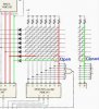
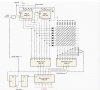
There's a 8-bit ring counter with 7 1s and a 0 preset and it shifts that 0 around the counter and applies it to every row at 5kHz, and theres the priority encoder to represent that state. When there's a key closure, a column is connected to a row, and when the 0 is applied to that row the column is also taken low, so the otherpriority encoder represents that state.

But my confusion is: when the key closure connects a row and a column because of the diode the input of the column encoder will be at 0, because no current will flow from the row to the column, it doesn't matter is the row is high or low, but it will from V+ to the row, and when the 0 is applied to the row connected there's always a 1 put in it from +V, right?.

So, I'm seeing something different than what says there, and that is, when there's a key closure and the 0 is applied to that row the cloumn is taken low too, and that way the encoders will represent that state, but what i see, is that always that there's a closure the column will be taken low independently on the state of the row (explained above), and when the 0 is applied to the row it will be taken high because of the connection to +V.

Thanks.
 

Attachments

  • 64.bit keyboard encoder.JPG
    64.bit keyboard encoder.JPG
    50.3 KB · Views: 408
hi,
The switches are normally open.

The '0' bit circulating in the 8 s/r takes each row low sequentially, whether or not a switch is pressed, also the corresponding switch Y plane line is taken low at the same time.

With no switches pushed the column inputs remain high, if a switch is pushed then when that Y plane line goes low the column line will go low.

OK.?:)
 
Last edited:
Thanks for the answer, I understand what you say the column inputs remain high when no swithc are pushed and the 0 is sequentially circulating for each row, but my confusion is, why if the 0 is put to some row it is not taken high by the connection to +V when the key is cloed? i mean ok it's low, but what happens with that closure? it is conected by the key to +V, right?

And why is it necessary to pull Low the row too when the key is closed to put the column low? I don't understand that, I mean if the key is closeed no current is flowing by the column, it flows throught the row, or the fact that there's a 1 in the row makes it not to flow there but to flow throgh the cloumn, if that's the answer for that question, the new question is why? what is the diode doing there?

I mean i can accept that and move on, but just accept it 'cause I'm not understanding.

Excuse me for the lot of questions, but I'm confused and I don't like leaving something without understanding.
 
Last edited:
Thanks for the answer, I understand what you say the column inputs remain high when no swithc are pushed and the 0 is sequentially circulating for each row, but my confusion is, why if the 0 is put to some row it is not taken high by the connection to +V when the key is cloed?
Because its columns are connected to +V via a resistors, not directly.

i mean ok it's low, but what happens with that closure? it is conected by the key to +V, right?

And why is it necessary to pull Low the row too when the key is closed to put the column low?
Because you need 6 bits to give 64 switch combinations and without the row going low how would closing switch pull the column low.?


I don't understand that, I mean if the key is closeed no current is flowing by the column, it flows throught the row, or the fact that there's a 1 in the row makes it not to flow there but to flow throgh the cloumn, if that's the answer for that question, the new question is why? what is the diode doing there?
If the diode wasnt there every time a row line was pulled low, [when a switch is pushed] all the other rows would be pulled low, you dont want that to happen,,, so the diode blocks that path.

I mean i can accept that and move on, but just accept it 'cause I'm not understanding.

Excuse me for the lot of questions, but I'm confused and I don't like leaving something without understanding.

hi,
Its ok to ask.:)
 

Attachments

  • 64.bit keyboard encoder.JPG
    64.bit keyboard encoder.JPG
    42.3 KB · Views: 365
Last edited:
Thanks for the answer, I understand what you say the column inputs remain high when no swithc are pushed and the 0 is sequentially circulating for each row, but my confusion is, why if the 0 is put to some row it is not taken high by the connection to +V when the key is cloed?
Because its columns are connected to +V via a resistors, not directly.
Ok I can see that, but then where goes the current? I mean the row is low and the column is connected to +V via a resistor, not directly. but that makes current not to flow to the row, and what makes the current not to flow to the column either? because taking the row low when the key is closed takes the column low too, haven't understand that

i mean ok it's low, but what happens with that closure? it is conected by the key to +V, right?

And why is it necessary to pull Low the row too when the key is closed to put the column low?
Because you need 6 bits to give 64 switch combinations and without the row going low how would closing switch pull the column low.?
My question is not that, it is How pulling the row low also puts the column low to? it's related to the first red question, where goes the current? why do I convert that 1 provenient from +V and nulle it puting row and column low?


I don't understand that, I mean if the key is closeed no current is flowing by the column, it flows throught the row, or the fact that there's a 1 in the row makes it not to flow there but to flow throgh the cloumn, if that's the answer for that question, the new question is why? what is the diode doing there?
If the diode wasnt there every time a row line was pulled low, [when a switch is pushed] all the other rows would be pulled low, you dont want that to happen,,, so the diode blocks that path.
I'm sorry but I don't see that, the why would the other rows be pulled low? where is the connection? the only path I see related to the diode is the one that connects it to the columns.
I mean i can accept that and move on, but just accept it 'cause I'm not understanding.

Excuse me for the lot of questions, but I'm confused and I don't like leaving something without understanding.


hi,
Its ok to ask.:)

Thanks.
I think I'm about to understand. But that's jus what I think.
 
hi,
Do you follow this.?
 

Attachments

  • AAesp01.png
    AAesp01.png
    11 KB · Views: 193
I realized something, maybe the cause of my missunderstanding is an or some unanswered questions that I have, when the output os the shift register is LOW it is demanding current, right? i assume that because when I see(that's my understanding) the key closed (green, right?), the way the arrow is headed is towards the S/R output, if it's that way I'm almost sure that now I can understand. And i see that when th key is closed and the row is high, there's no demand of current and it goes through the column, and when the row is pulled low it demands current and that way the column is pulled low too.
If that's the explanation, then I understood. If it's not, then I'm not there yet.

Thanks.

hi,
The S/R acts as a 'current sink' when the pin is low, this means it will pull the pin and the switch line low.

It looks as though as you have got the idea.:)

The input pins of the Row and Col ic's just follow the voltage level on the row and col lines, as they are inputs.

If the diodes were not present, then say two switches are pushed on different rows you would connect 2 of the S/R output pins together which is not recommended. The diodes prevent this.

Anymore questions.?
 
Last edited:
Thank you very much, the diodes prevent that together with the fact that there is only one 0 moving around the counter, right? because if there were another 0 then diode wouldn't prevent anything if I pressed another key.

I had that confusion for some time, I even start a thread based on that, in this same forum.

So let me corroborate: when the output is HIGH it suplies current and when it's LOw it sinks it. I would like to ask you something that was never answered in that thread, why in the datasheets, that current in the LOW level has a plus (+) and in the HIGH level it has a minus (-), I thought that that (-) is because in the HIGH level it demands current, and the opposite happened in the LOW level, because I've read in many other sites and Digital Systems Textbooks, that the current in the LOW level was higher than in the HIGH level, (what I don't remember is if that was only with CMOS chips).

Thanks again.

hi,
In that datasheet was the statement referring to an input or an output, also was it a TTL datasheet.?
Do you have a copy of that d/s to post.??
 
It was referring to an output, and it's a CMOS.
Here it is.
I struggled with that.

hi,
Extract from the Manufacturers Specifications:

Positive current is defined as conventional current flow into a device.
Negative current is defined as conventional current flow out of a device.
 

Attachments

  • AAesp03.gif
    AAesp03.gif
    3.6 KB · Views: 152
Thank you very much, fog dissipated.

That wasn't one of the notes, right?
I'm looking it up and can't see it.
 
Status
Not open for further replies.

Latest threads

New Articles From Microcontroller Tips

Back
Top