Continue to Site

Welcome to our site!

Electro Tech is an online community (with over 170,000 members) who enjoy talking about and building electronic circuits, projects and gadgets. To participate you need to register. Registration is free. Click here to register now.

  • Welcome to our site! Electro Tech is an online community (with over 170,000 members) who enjoy talking about and building electronic circuits, projects and gadgets. To participate you need to register. Registration is free. Click here to register now.

A little basic help please

Status
Not open for further replies.
oh and just for clairification for me, A123 says that they are a forgiving cell and will take charges from 2-3.6V so it seems that under voltage is less of an issue than over. so really if i supplied 10-11V the system would still be good.?. correct?
 
browningbuck,

A single A123 Cell ...
2 Volts is a Fully Discharged (do not let it go below-bad)
3.3 Volts is Fully Charged - Nominal Volts (open)
3.6 Volts is charging and is 100% complete

A123 - 4 Battery Pack ...
8 Volts is a Fully Discharged (do not let it go below-bad)
13.2 Volts is Fully Charged - Nominal Volts (open)
14.4 Volts is charging and is 100% complete

A123 - 4 Battery Pack with Blocking Diode
8.7 Volts is a Fully Discharged (do not let it go below-bad)
13.9 Volts is Fully Charged - Nominal Volts (open)
15.1 Volts is charging and is 100% complete

These voltages are non-negotiable.

To get a fully charged battery pack your Solar Cell or booster
needs to supply (4 x 3.6v) + 0.7 (diode) = 15.1 Volts.
10 - 11 Volts will do little or no charging.
You want a 100% Fully Charged Battery Pack, right?

Have you measured the Voltage of a 100% Fully Charged Battery Pack.
Is it 13.2 Volts?

Have you measured the Voltage of a Fully Discharged Battery Pack?
Is it 8 Volts (approx) ?

Yes, you can START charging a single Cell at 2 Volts (each) but
as the battery voltage rises (gets more of a charge)
then the Charging Voltage must also rise to continue the charging process
until each Cell reaches 3.6 Volts (fully charged) then stop.

The charging voltage must always be MORE than the
open battery voltage to continue the charging process to 100%.

OK ?
 
Last edited:
Yes, you can START charging a single Cell at 2 Volts (each) but
as the battery voltage rises (gets more of a charge)
then the Charging Voltage must also rise to continue the charging process
until each Cell reaches 3.6 Volts (fully charged) then stop.

The charging voltage must always be MORE than the
open battery voltage to continue the charging process to 100%.

OK ?

ahhhh yesss i see
 
so i guess what i really should do is put this new 12V (hopefully this already acounts for the diode since one should already be built in to it) solar panel in series with the smaller solar panel and create the optimal voltage for the cells
**broken link removed**
 
and spindrah please dont underestimate people. i can build something that is already drawn, it was coming up with an idea that was out side the box. sorry that this thread was such a bothersome ordeal for you, but since you are on a forum there is some common edequate that your mom should have tought you "if you dont have nothing nice to say, dont say anything at all"...

I am not underestimating you! I understand you have no electronics knowledge at all, and i was telling the other guy he cant just say "use a dc-dc converter" because that means nothing to a guy with 0 electronics knowledge. you say you can "build something that is already drawn" , thats why i said he needs to give you step by step help.

here is something you should learn about the internet, get ride of your extremly THIN SKIN and you will learn from people like me

i didn't say anything rude, i simply tried to help you.
 
Last edited by a moderator:
If it matters, I wrote: "Either rewire the solar for 12V (you'll actually need more than 12V to meet the charging requirement of the batteries) or build a 3V->12V boost converter."

I expected that if OP chose the latter, a request for more help would be forthcoming. As it turns out, the help was offered before requested, and it could have ended there.
 
I am not underestimating you! I understand you have no electronics knowledge at all, and i was telling the other guy he cant just say "use a dc-dc converter" because that means nothing to a guy with 0 electronics knowledge. you say you can "build something that is already drawn" , thats why i said he needs to give you step by step help.

here is something you should learn about the internet, get ride of your extremly THIN SKIN and you will learn from people like me

i didn't say anything rude, i simply tried to help you.

i dont have thin skin and you didnt provide any information for me to learn from hence the reason i told you to keep your mouth shut. however if you would have contributed like the other two members, i would have just taken the remarks.

well guys thank you and i will post up the final product soon(this idea was only part of the whole design) hopefully it all comes out to the quality that i expect.

once again thank you for your help and time ;):D
 
Last edited:
Why is everybody talking about a 3.0V to 3.6V battery??
The A123 cell is a lithium-ion cell which is similar to a Li-Po cell.
They are 4.2V when fully charged and are 3.0V when dead.

Since four cells are in series then a "cell balancing" charger circuit is needed to avoid a fire. Each cell must not be allowed to exceed 4.2V and the charging current must be turned off when the charging current becomes low.
 
My research shows that the A123 Battery should be fully charged at only 3.6 - 3.7 Volts not 4.2 Volts. This is one of many differences between an A123 Cell and a standard Li-Po Cell. Not much damage will occur if you charge an A123 Battery to 4.2 Volts one time but continuous charging to 4.2V is not recommended - it reduces the longevity of the A123 Cell. I ask you, "Why would you want to do any damage to the A123 Cell?" Therefore, a different charger (with a lower cutoff voltage from CC to CV) is recommended for A123 Cells vs. standard Li-Po Cells. When the Charger is removed the Nominal Open Voltage of an A123 Cell is 3.3 Volts and standard Li-Po is 3.7 Volts (another difference)

Yes, I did explain in an earlier post that charging Cells in Series was more difficult than charging individually. But given the very low charging rate I think it will be OK. The A123 Cells are more forgiving when Series charged vs standard Li-Po (another difference).

A123 Cells do NOT burst into flames when over charged like standard Li-Po Cells (another difference).

I could go on with the differences between A123 Cells and standard Li-Po cells but you can do that research yourself.

A Balanced Charger circuit may be possible by using 4 @ 3.6Volt Zener Diodes, a small current limiting Resistor, the Blocking Diode and the Solar Panel. Each Cell would then have it's own Charging Circuit with 3.6V Cut-Off. Let's wait and see what browningbuck designs.

This is from one Battery Charger manufacturer (others are very similar) ....

Standard LI-Po Cell setup ...
Change from Constant Current to Constant Voltage at 4.18 Volts
Fully Charged at 4.2 Volts

A123 Cell setup ...
Change from Constant Current to Constant Voltage at 3.6 Volts
Fully Charged at 3.65 Volts

OK ?
 
Last edited:
You are correct.

I found an article about "A123" cells that was wrong. It described ordinary Lithium-ion cells in a laptop battery pack.

The real A123 cells are made only by A123 Systems and are different from ordinary lithium cells.
 
okay whole new thing in the mix, i bought the 12V solar cell thats in the link above, BUT in dim light it creates 12v and in direct its at 22V... so i am thinking that i would need to put a voltage reg on there. what does the group think?
 
Your solar panel has a high output voltage when its current is nothing (no load).
It has a high output current when its voltage is nothing (it is shorted).

But a rechargeable battery needs both voltage and current at the same time.

Measure the voltage and current from your solar panel when it has a load similar to your battery.
 
Last edited:
browningbuck, This simple circuit might work to regulate the Max Voltage as the Battery becomes charged. Prototype it. Put the Solar Cell in the sun. Connect the battery (put in shade). Then over time use a DVM to measure each cell to make sure none goes above 3.6 - 3.7 Volts as overall Battery Voltage approaches 14.4. It should then Float at 14.4V and hold the 4 Cell A123 at full charge. Report back how how long it takes to get to 14.4 Volts or if it exceeds 14.4V or never reaches 14.4 V. The Zener will get warm if the Solar Cell is in the Sun and Battery is fully charged or no battery connected. If you change the Solar Cell with one with more ma then you will need to increase the Wattage of the Zener, too.

OK ?
 

Attachments

  • A123 Solar Charger.jpg
    A123 Solar Charger.jpg
    28.7 KB · Views: 900
Where can you buy a zener diode that has the accuracy needed for charging a lithium battery?
How will you balance the charging so that each cell charges to the same level?
 
A lot of folks have a misperception of 'voltage' of a PV panel.

You can take a panel that has an open circuit voltage of 22 vdc and charge a 3.7 v battery or charge a 15v battery with it, as long as its peak illumination current doesn't exceed battery max charge current rate.

The simplest model for a silicon solar cell is an illumination based current source that is voltage clamped with a parallel diode. When no external load is applied to cell, all the illumination generated current just goes down the inherent diode of the cell creating an open circuit voltage of the diode drop.

You must understand the temp characteristic of a diode to understand why a certain number of cells are hooked in series for a given target battery voltage.

It is desireable, but not absolutely necessary, to pull the illumination current off at the maximum voltage possible, which is just as the inherent diodes barely starts to conduct. This gives the maximum power from the cell. At 25 deg C, the unloaded voltage across the diode when all the cell's current is passed into it is about 0.65 vdc. This is well into diode conduction so the maximum power loading where about 3% of the illumation current goes down the inherent diode is just slightly over 0.5 vdc per cell.

Now if you know what happens to a silicon diode forward voltage drop over temp you understand the margin that must be put into the number of cells stacked to ensure the PV panel's net useful voltage stays above maximum required charger battery voltage. In full sun, in the heat of summer, with significant cell heating, the diode conduction voltage can be less then 0.5 vdc yielding a max power point on cell of about 0.4 vdc. When it is cold, the effect is opposite and you may end up with a cell max power point of over 0.7vdc.

Typical PV panel to charge a 12v lead acid, which requires a 13.2vdc float voltage and 14.4vdc bulk voltage, is typically 36 cells in series. This also happens to be about the same requirement for four A123 cells in series.

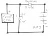
You always need a charge controller to prevent overcharging and current backflow when dark. The simplest PV charge controller, known a PWM controller, just has a series switch that opens the connection to the panel when the max battery charge voltage is reached. It then just duty cycles to maintain the average desired charge voltage on the battery. Remember the panel is acting as an illumination based current source.

You can also make a charge controller with a shunt regulator but it must be able to dissipate all the power the PV panel produces. In your four A123 cells this would be a shunt regulator of 14.6 vdc.

You also don't want a cell size that produces a current at full sun that exceeds the max charge current of the battery being charged. A good quality cell produces about 35 mA per sq. cm. area at full sun intensity.
 
audioguru,
There is an easy way to either increase or decrease the Max Voltage across each cell by approx +/-0.1 Volts. That is why I asked browningbuck to prototype this circuit, turn it on and then actually measure with DVM to see what happens. After the measurements, then we can make a simple adjustment, if needed. Browningbuck used these words: "simple" and "easy". Lets not over complicate this design.

The Solar Cell purchased produces only 420 milliwatts. My all passive (easy/simple) circuit consumes 35 milliwatts leaving about 400mw to charge the battery pack (almost 92% efficient).

Given that the A123 is not being discharged at 5 - 10 Amps nor being recharged at 5 - 10 Amps (more like 16 - 34 ma), I do not think cell balancing will be an issue.

Can you design and post a (easy/simple) "Balanced" 4S A123 Charger that actually runs from the 12V 34ma Solar Cell, is over 90% efficient and does not discharge the battery when the Solar Cell is dark? That is quite a challenge.
 
Last edited:
wow summit, NICE post, i of coarse will be monitoring cell voltage. small disclaimer: this isnt something that will not see much use, its a man toy, and will have an on off switch that most of the time the cells will be removed from the system and all it will do is collect dust.

when it is on the most work it will do is power a small amp i wired up, and then the hardest it will work is powering a 12v car plug in (in case you want to charge an i pod). it will sit on the desk and be more of a working conversation piece).


and as a side note, the woodwork has come together nicely so far.
 
Last edited:
I have never seen a battery charger circuit that balances the charging of series lithium cells. Maybe Maxim has an IC that does it.
 
Status
Not open for further replies.

Latest threads

New Articles From Microcontroller Tips

Back
Top