Continue to Site

Welcome to our site!

Electro Tech is an online community (with over 170,000 members) who enjoy talking about and building electronic circuits, projects and gadgets. To participate you need to register. Registration is free. Click here to register now.

  • Welcome to our site! Electro Tech is an online community (with over 170,000 members) who enjoy talking about and building electronic circuits, projects and gadgets. To participate you need to register. Registration is free. Click here to register now.

A few questions about the Mod4 FM Tx

Status
Not open for further replies.

Birdman Adam

New Member
I've been looking into building an FM transmitter recently and discovered audioguru's Mod4 circuit. It seems to be one of the best on the internet (I've searched through a lot)! I will be using the stereo input addition, and I am wondering what kind of wire I must use for the coils. I know enameled copper wire is usually used but I can't seem to find where to purchase it or get it from another device. I also read that normal #24 AWG hookup wire can be used. Is this true? And if so, will performance be affected if I use it? Finally, is it okay if I power the whole circuit from 5 volts (including the last part). I am guessing that the output range will simply be less.

Thanks!
 
I used 1mm enamelled copper wire from the crossover coil of a speaker to make my coils. They look like this:
If you use different size wire then the tuned frequency range will be different.

I never tried my FM transmitter circuit powered from 5V. Its range will be reduced.
 

Attachments

  • FM coil.GIF
    FM coil.GIF
    5.6 KB · Views: 158
24AWG won't be mechanically stable like 1mm wire. Its frequency will change with the slightest vibration. Electrically, it will work just fine.
 
Darn, I can't seem to get it working... I got everything soldered together on prototyping board being mindful of keeping all of the components close. I have already examined my board for any shorts or wiring mistakes, (I don't think I missed anything). I plugged it into the headphone output of my computer and turned it on, with a radio nearby on an empty station. I have tryed tuning it by rotating Q2's trimmer cap, but to no avail.
I know I should be using a ceramic or plastic screwdriver because the stray capacitance will mess it up otherwise. My radio is about 20 ft away from me when I'm trying to tune it. I know the computer output is working because I can use normal headphones with it.
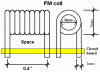
Also, I know I got a good connection with all of my components and the headphone wire. While tuning, I could have sworn I faintly heard the music being received once or twice, but then it would go away before I could confirm. Other times while spinning the trimmer cap, other stations would start to come in clearer. I think it's oscillating, because if I tap the trimmer cap with a metal screwdriver, I can hear it on the radio. I am using a 30" long antenna and my circuit is 2cm X 5.5cm. I know a steady 5 volts is going to the main circuit, and 9 volts is going to the last amp stage. Following are voltages for the three transistors while supposedly transmitting music:

My multimeter says it's drawing about 10-12 mA.

Q1-Vc = 2.58V
Q1-Vb = 0.75V
Q1-Ve = 0.1V

Q2-Vc = 5.23V
Q2-Vb = 1.58V
Q2-Ve = 1.29V

Q3-Vc = 9.7V
Q3-Vb = 0.75V
Q3-Ve = 0.05V
 
The input audio is a few milli-volts from an electret microphone, not the huge signal from an earphones jack.

The tuning capacitor must be turned by a non-metallic tool.

Your radio receives other stations clearer when the transmitter is tuned because your radio is cheap and is overloaded by the stong signal from the nearby transmitter.

My Mod-4 transmitter draws 53mA from 9V.
 
Hey Birdman? Do you have a scope? If it is oscillating it is probably not on frequency. A frequency counter would come in handy as well.
 
I used to stereo input addition to attenuate the signal from my computer. I do not have a scope. If I'm measuring the current correctly, then it reads 11 mA, but when I touch one of the caps with a metal screwdriver, it goes up to 48-55. I think I need to check all of my component values and connections...:mad:
Maybe I will take the radio outside and get like 30 yards away and then try to tune it. To confirm, are the transistor voltages correct (or close)? Thankis for all the help so far. I've learned a lot from this project!
 
Last edited:
I cannot measure the voltages on my transmitter because the capacitance of my meter's probes stops the circuit from working. There are a couple of voltages that can be simply calculated and yours are fine.
 
Ok well that's good news. By the way I was measuring current wrongly, so it did come out to about 53 mA. I'm gonna test for wrong connections and component values and hopefully I'll figure it out...:) Thanks again!
 
Status
Not open for further replies.

New Articles From Microcontroller Tips

Back
Top