Continue to Site

Welcome to our site!

Electro Tech is an online community (with over 170,000 members) who enjoy talking about and building electronic circuits, projects and gadgets. To participate you need to register. Registration is free. Click here to register now.

  • Welcome to our site! Electro Tech is an online community (with over 170,000 members) who enjoy talking about and building electronic circuits, projects and gadgets. To participate you need to register. Registration is free. Click here to register now.

A few issues with generating composite PAL using logic IC's

Status
Not open for further replies.

PConst167

Member
Hi friends,

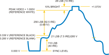
I have finished working on a simple video card that generates sync pulses for PAL/CCIR monochrome televisions. Apparently I have gotten the TV to sync to my signals, however, I was hoping to be able to control the brightness of the screen with my circuit in order to confirm that the TV was really obeying the circuit. Here's the problem! The TV only shows a white screen. I don't know how to manipulate the voltage in order to lower it and match the TV's requirements.

My signals stay constant at around 4.5V, and then at sync times they go to 0V. What should I do to them to be able to fit them to the TV's requirements for composite PAL?

Some sources say the sync pulses are -0.3V rather than 0V. Some say it's 0V. I tried inverting the signals to see what happens and what I see on the TV are lots of little horizontal white lines in a black screen, and a thick white line at the bottom. Since this is the inverted signal, does this mean that the original signal is correct? Since if the inverted one was correct, it wouldnt show the white lines everywhere.

I appreciate your help.

Paul
 
Some sources say the sync pulses are -0.3V rather than 0V
Because the video is most likely AC coupled it does not matter. It is best for you to use 0V.
My signals stay constant at around 4.5V, and then at sync times they go to 0V. What should I do to them to be able to fit them to the TV's requirements for composite PAL?
Use a resistor divider.

350px-Composite_Video.svg.png
 
I went back to 1986 and found a design I did. Back then I did this many times.
On the right side is the TV with the 75 ohm termination resistor and capacitor.
On the left is a digital IC. Fast CMOS works well but TTL will work. CMOS = 0/5V while TTL does not pull up well.
For sync: sync=0, V1,V2,V3=000 The output voltage is 0 volts.
For not sync, (black level): sync=1, V1,V2,V3=000. (wild guess, The resistor on "sync" might be about 750 ohms to get about 0.3V)
The resistors on V1,V2,V3 are sized to get about 1 Volt on the output when V1,V2,V3=111 and sync=1.
This design gives a sync level of 0V, black level of 0.3, and video has 8 levels from black to white.
upload_2017-1-15_19-49-2.png
 
I went back to 1986 and found a design I did. Back then I did this many times.
On the right side is the TV with the 75 ohm termination resistor and capacitor.
On the left is a digital IC. Fast CMOS works well but TTL will work. CMOS = 0/5V while TTL does not pull up well.
For sync: sync=0, V1,V2,V3=000 The output voltage is 0 volts.
For not sync, (black level): sync=1, V1,V2,V3=000. (wild guess, The resistor on "sync" might be about 750 ohms to get about 0.3V)
The resistors on V1,V2,V3 are sized to get about 1 Volt on the output when V1,V2,V3=111 and sync=1.
This design gives a sync level of 0V, black level of 0.3, and video has 8 levels from black to white.
View attachment 103597


Thanks but for some reason that just doesn't work for me. You see where you have those resistors to create a voltage? I have just a single resistor set up to give 0.3V at the output when my sync level is 1. When my sync is 0 then the output is 0V.

This doesn't work on my TV....

I think my TV might not actually be AC coupled. Why ? Because I attached a 222 ceramic cap to my output, and that removed my DC component and brought my sync level to around -4V, which made the TV finally "work".... However this differentiates the output because of the 75Ohm internal.

I took a superNes console that works on this TV, looked at its video output on the scope. Its signal has a negative amplitude for the sync signal... This is defo the reason my signal doesnt work and the reason why when i attach the cap it works.

I need a way to make a negative amplitude for my sync... Please help
 
Last edited:
I think my TV might not actually be AC coupled.

It doesn't have to be, the source should be AC coupled.

So... What to do ?

Add a suitable sized capacitor on the output of your source - it needs to be pretty large though.

Or, if you've got full access to the monitor, then add a smaller capacitor AFTER the 75 ohm load resistor.
 
It doesn't have to be, the source should be AC coupled.


Add a suitable sized capacitor on the output of your source - it needs to be pretty large though.

Or, if you've got full access to the monitor, then add a smaller capacitor AFTER the 75 ohm load resistor.


Tried that. Almost worked. You know what I think ? I think my TV is taking the voltage level at the back porch as the WHITE reference rather than black! Usually TV's take the black reference there, but my tv seems to be doing the opposite! I say this because there is a little bump right after the sync, then the voltage goes down VERY slowly, and the result on the TV is that on the left side it starts as white, then as it goes to the left it goes grayer.

Could this be ?
 
Well you're pretty vague about EXACTLY what you're doing, but a video signal is analogue, so you need to use some kind of D2A to create it from your logic levels - such as the resistor network mentioned above.
 
Start over!
Where are you connecting to the TV? "Antenna" or "Video"

The sync stripper is "AC coupled". Depending on the definition of AC. LOL It looks at the most negative voltage. It does not care what that level is. I have designed sync strippers for many companies. Usually they requires +/- 1 volt range specs. But I can't remember any of them not working over a much wider range. So 0V or 0.3V or 0.5V should not make any difference. The circuit looks for the most negative signal and sets that as sync. Then what level right after sync is set as black. In video there is a assumption that "ground" has been lost and must be reestablished by clamping to black level.

on the left side it starts as white, then as it goes to the left it goes grayer.
If a picture goes from white to gray in one line then you must have change the input cap.
Do you have a scope? I take pictures with my phone and post them. I think we are beyond words here.
 
A 222 cap and a 75 ohm terminating resistor equals a corner frequency of 965 kHz. The lowest frequency of interest in a monochrome PAL video signal is 25 Hz. Whatever the problem is, the coupling cap is 100,000 times too small so it totally distorted your signal. This is shown clearly in the scope image.

On the chip producing your signal there are little letters and numbers printed on the top of the chip. What are they? If there are two rows of little letters and numbers, please post them as they are on the part.

ak
 
Maybe you have "sync" inverted. How long (in time) is your signal at 0V and how long is it at 0.3V?
AND
Don't modify your TV. It is not the problem.
 
I went back to 1986 and found a design I did. Back then I did this many times.
On the right side is the TV with the 75 ohm termination resistor and capacitor.
On the left is a digital IC. Fast CMOS works well but TTL will work. CMOS = 0/5V while TTL does not pull up well.
For sync: sync=0, V1,V2,V3=000 The output voltage is 0 volts.
For not sync, (black level): sync=1, V1,V2,V3=000. (wild guess, The resistor on "sync" might be about 750 ohms to get about 0.3V)
The resistors on V1,V2,V3 are sized to get about 1 Volt on the output when V1,V2,V3=111 and sync=1.
This design gives a sync level of 0V, black level of 0.3, and video has 8 levels from black to white.
View attachment 103597


DAMN!!!! IT FIANLLY WORKED !!!!!!!!!!!!!!!!
 
A 222 cap and a 75 ohm terminating resistor equals a corner frequency of 965 kHz. The lowest frequency of interest in a monochrome PAL video signal is 25 Hz. Whatever the problem is, the coupling cap is 100,000 times too small so it totally distorted your signal. This is shown clearly in the scope image.

On the chip producing your signal there are little letters and numbers printed on the top of the chip. What are they? If there are two rows of little letters and numbers, please post them as they are on the part.

ak


you are here !!!!! thank you buddy. They banned me from the other forum because I didnt want to show the schematics I didnt have. They are crazy. Thanks for coming here.

It has finally worked!!! The problem was that the TV was taking the first voltage after the synch as the reference for white rather than black, and because I was keeping the voltage constant, it would only show white, even if the voltage was zero!! Then I tried varying the voltage with a counter and it finally worked !!!

**broken link removed**
 
Maybe you have "sync" inverted. How long (in time) is your signal at 0V and how long is it at 0.3V?
AND
Don't modify your TV. It is not the problem.


The TV was taking the first voltage after synch as the reference for white, and because I was trying to make it black by lowering the voltage to zero, it would always show as white!!! I finally realized it was doing this strange thing and tried varying the voltage after the synch, and it has finally worked!!!!!!!! Thank you buddy !!!!!!!!!!!!!!!!! This is amazing !

I been trying this for almost a month now !!!!
 
I also removed all the caps from my output. I opened the TV and saw it had a 68 ceramic capacitor connected to one of the legs of the video input. I think it was the ground leg because the other leg was going into an IC. Is it the same to AC couple it from the ground input connection rather than the signal input in the composite cable ?
 
It is common for the video signal to go to two places. (video amp) and (sync stripper)
The termination resistor is 75 ohms.
In side the TV the video amp is probably much higher impedance so a small cap is fine.
The sync stripper needs a small cap also.
You might have a IC that has everything in one part.
----------------------
I didnt want to show the schematics
It really helps if you can post even a small part of the schematic. Like post #4.
AND
A picture of you output signal would have help. Picture=1000 words.
(for next time)
---------------
Glad you are happy. LOL
 
A 222 cap and a 75 ohm terminating resistor equals a corner frequency of 965 kHz. The lowest frequency of interest in a monochrome PAL video signal is 25 Hz. Whatever the problem is, the coupling cap is 100,000 times too small so it totally distorted your signal. This is shown clearly in the scope image.

On the chip producing your signal there are little letters and numbers printed on the top of the chip. What are they? If there are two rows of little letters and numbers, please post them as they are on the part.

ak


Little letters and numbers........... All my chips are the 74HC series.... I'm not that noob :)
 
It is common for the video signal to go to two places. (video amp) and (sync stripper)
The termination resistor is 75 ohms.
In side the TV the video amp is probably much higher impedance so a small cap is fine.
The sync stripper needs a small cap also.
You might have a IC that has everything in one part.
----------------------

It really helps if you can post even a small part of the schematic. Like post #4.
AND
A picture of you output signal would have help. Picture=1000 words.
(for next time)
---------------
Glad you are happy. LOL


I don't have the schematics... I built it from my big head to try it out :)

Is it possible for me to bug you on skype (text) sometimes ?
 
Status
Not open for further replies.

Latest threads

New Articles From Microcontroller Tips

Back
Top