Electro Tech is an online community (with over 170,000 members) who enjoy talking about and building electronic circuits, projects and gadgets. To participate you need to register. Registration is free. Click here to register now.
Welcome to our site! Electro Tech is an online community (with over 170,000 members) who enjoy talking about and building electronic circuits, projects and gadgets. To participate you need to register. Registration is free. Click here to register now.
good need help with the ADC of this pic I'm starting to, I just want a basic conversion without interruption for now, seriously any help would be welcome, thanks for your help
beyond that, can't provide much more help as you haven't described where you might be stuck, what compiler you're using or even what language you're looking to write your code in.
Try this code, its taken from my working program.
Have only built it, but it should run ok on hardware or Sims - use a 10k pot / trimmer as your adc input for your basic tests. so you can check the voltage with a dvm and then see if your adc result agrees with the voltage measured.
WP100've tested and reviewed your code and I have produced nothing, not that I'm making the mistake your code is similar to mine, I think qeu use similar settings ADCON records ...
well I'm using a 10K potentiometer, with its ends connected to 5V and ground and pin an0 average, I've also seen you use the 4MHz internal oscillator so the pic is only made with LEDs and the cable connecting the an0 pin to pin of potentiometer means ......
or did I miss something? please tell me
and also wanted to ask if you've tried? normal work for you? seriously help me a favor ...
Well have just run the code I sent on the hardware via the Pickit2 Debugger and it works fine.
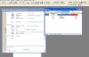
You can see it working on the screenshot.
In the 'watch' window you can see the adc result from the first adc reading has been transfered to the two user registers, I allowed it to do another reading but after a moved the 10k pot to a new posisition.
ADRESL and H now show the new value.
( with debugger you can stop and start the program as you like so you can see whats happening)
I have added onto the original code so that when it has done the adc routine it flashes a led on and off for 1 second on RB0, then it loops around to the adc again.
If your hardware is set up correctly it should seem to act as a simple led flasher.
I have run this code directly on the chip, not via the debugger, so you should get the same results if your hardware is ok.
Does it do that for you ? - if not send your actual assembler code back with a diagram of how your hardware is connected.
On the 4620 pins 32 and 11 should be VDD + and pins 31 and 12 VSS -.
This site uses cookies to help personalise content, tailor your experience and to keep you logged in if you register.
By continuing to use this site, you are consenting to our use of cookies.