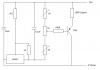
Continue to Site

Welcome to our site!

Electro Tech is an online community (with over 170,000 members) who enjoy talking about and building electronic circuits, projects and gadgets. To participate you need to register. Registration is free. Click here to register now.

  • Welcome to our site! Electro Tech is an online community (with over 170,000 members) who enjoy talking about and building electronic circuits, projects and gadgets. To participate you need to register. Registration is free. Click here to register now.

A bit of advise on 4 to 20mA!

Status
Not open for further replies.

Ian Rogers

User Extraordinaire
Forum Supporter
Most Helpful Member
I built this:-

upload_2016-2-17_13-25-35.png


Works as expected but for thermal runaway at 20mA... I used a medium power PNP that can dissipate 600mW (ish)..

24 * .02mA = 480mW so I wasn't surprised with the thermal drift.... I have since replaced the PNP with a high power darlington, but at 20mA there is still some thermal drift... What would stabilize the PNP??? A heat sink didn't work.. The slightest temperature change seems to matter a great deal... The 5.6V out of the LM337 is solid!! Running at 12v is perfectly okay...
 
hi,
This is a LTSpice sim 0C thru 50C, minute change only.

The resistors are specified as 0,01%

What is the spec on the components.?

Eric
 

Attachments

  • A07.gif
    A07.gif
    32.5 KB · Views: 186
Hi,
Are you making a 4/20mA test source, where the the 1K pot Sets the output current.?
This shows the effect of stepping the pot from 10% to 90% rotation and the tempr from 0C thru 50C
E
 

Attachments

  • A09.gif
    A09.gif
    23.2 KB · Views: 185
Thanks for looking Eric.... I can't get my head around it!! First I used a BC212, but that just got VERY hot!

Then I used a STX790A That just drifts with anything over 8mA..
I have now a TIP125 darlington.... There is slight drift.. When it sits at 20mA... after about 5 seconds it has climbed 0.15mA.... If I place my finger on the tab, it slows and cools ever so slightly!! (Hence the heat sink )!! But it still drifting..

Yes I have two presets and a 1k linear pot.... I need the high resistance values so the residual current doesn't exceed 4mA..
 
hi,
This is with a TP125 , the top plot is the TIP's heating/power

EDIT:

The 2nd image shows that the current is slightly load sensitive. [rt stepped]
 

Attachments

  • A10.gif
    A10.gif
    23.4 KB · Views: 177
  • A11.gif
    A11.gif
    23.4 KB · Views: 186
Last edited:
Hi Ian,
I think you problem is related to the fact that the base emitter voltage of the transistor will vary by 2 mV per degree C. (Drops by 2 mV for every degree C rise.) As your circuit is comparing the voltage across the 100 ohm resistor + VBE with the reference voltage then as the junction heats up you are effectively adding 2 mV per degree C to the reference voltage.

Edit.
I think just using the LM337 with a variable resistor between the output terminal and the adjust terminal (62.5 ohms for 20 mA, 315.5 ohms for 4mA) with its input to neg. and the adjust terminal to pos. would work better. You would probably need a capacitor between input and adjust to prevent oscillation. (An LM317 would also work in this way with the polarities reversed.)

Les.
 
Last edited:
Hi Ian,
I think you problem is related to the fact that the base emitter voltage of the transistor will vary by 2 mV per degree C. (Drops by 2 mV for every degree C rise.) As your circuit is comparing the voltage across the 100 ohm resistor + VBE with the reference voltage then as the junction heats up you are effectively adding 2 mV per degree C to the reference voltage.

Les.
So what can I do...

If I use an XTR116 the same transistor I use is the BC212 and that is as stable as steel!!.... So this means that the problem IS the resistor... Usually these 15ppm 100 resistors do not get warm!!... ( or at least, they don't look liker they do )...
 
hi Ian,
I seem to have unexpected result on my sim, never seen the problem before???
If I use shortened version .step temp 0 50 5 I get a an expected change in circuit current, but when I use the usual .step param temp 0 50 5 I get no current change!!!

I will double check the sims.
E
 

Attachments

  • A11.gif
    A11.gif
    23.1 KB · Views: 173
Hi Ian,
I had not come across the XTR116 before so I looked at the data sheet. If you look at the internal circuit you will see the raw voltage across the sense resistor (R2 25R) is used. It does not have the base emitter junction voltage in series with it so the temperature of the transistor will not effect the current. NOTE I added a suggestion to my last post (#6) that you may not have read.

Les.
 
think just using the LM337 with a variable resistor between the output terminal and the adjust terminal (62.5 ohms for 20 mA, 315.5 ohms for 4mA) with its input to neg. and the adjust terminal to pos. would work better. You would probably need a capacitor between input and adjust to prevent oscillation. (An LM317 would also work in this way with the polarities reversed.)

Not linear though!! Tried it! I'm ditching this and I'm going to use an XTR116 coupled to a 20k pot!!!

Thanks for looking at it though!!! Cheers Les and Eric..
 

Attachments

  • upload_2016-2-17_15-54-54.png
    upload_2016-2-17_15-54-54.png
    8 KB · Views: 168
Could you use a high-side comparator instead of the LM337, with the comparator's inputs fed directly from the 100R sense resistor? That would eliminate the transistor from the control loop.
 
You need feedback to control the drift, a 'free floating' current source is obviously going to drift all over the place, as there's nothing to stop it - essentially Vbe varies with temperature, so it's pointless providing a fixed voltage for the base.

Use an opamp to monitor the voltage across the emitter resistor and alter the base feed accordingly - am LM337 isn't a good choice for something like this.
 
hi Ian,
I have modified a circuit I did some time ago, its a little more complex than your original but its thermally stable.
Adjustable 4mA thru 20mA.
The R2 [250R] is the load resistor.
E
 

Attachments

  • A12.gif
    A12.gif
    26.3 KB · Views: 195
  • A13.gif
    A13.gif
    26.3 KB · Views: 185
You need feedback to control the drift, a 'free floating' current source is obviously going to drift all over the place, as there's nothing to stop it - essentially Vbe varies with temperature, so it's pointless providing a fixed voltage for the base.

Use an opamp to monitor the voltage across the emitter resistor and alter the base feed accordingly - am LM337 isn't a good choice for something like this.
That eplains quite a lot..

My other system has a dac output with a feedback onto that resistor to monitor the voltage... I can keep the voltage at exactly 2V... I should have converted this device.... The only problem with that one is that it sinks the current!!! I need a closed loop that sources the current!!
 
Here's my offering. D1-D3 drop the opamp inputs down so that they're within the common-mode range of a common-or-garden comparator. Current shown is for end-to-end variation of the pot wiper. Plots show output is stable over a -20C to +40C range.
4-20mASource.PNG
 

Attachments

  • 4-20mASource.asc
    2 KB · Views: 135

Attachments

  • AD694.pdf
    208.9 KB · Views: 164
  • A08.gif
    A08.gif
    35.3 KB · Views: 192
Last edited:
I've gone with MikroE's 4~20mA design.... Fully isolated with 12bit resolution.. I can calibrate the 4 and the 20mA to whatever I want... Works brilliant!!
upload_2016-3-4_14-29-55.png

I can use the XTR115 or the XTR116 as I set vref at 5V not 2.5v or 4096v...

Thanks for your replies....
Incidentally!! I forgot C3 in my design!!! Don't or it is as unstable as RK's designs!!
 
Status
Not open for further replies.

New Articles From Microcontroller Tips

Back
Top