MrDEB
Well-Known Member
Nice find BUT!
the relay is rated for 20 amps and the thermostat is for cold apps not hot.
Last night while waiting to take inventory of my eyelids (sleep) I thought about all the pros and cons of what I am trying to accomplish.
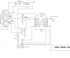
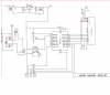
Well instead of the comparator, 555 timer etc. I decided to go with a PIC.
one PIC (18F1320 as I have several on hand and then use Swordfish basic)
one thermo-resister
can add an LCD readout and using the PIC I can get long relay ON times.
considerations = 30 feet of wire between PIC location and relay. Worry about electro-flux over the long distance
Thinking opti coupler at relay location then have the PIC control the opti coupler. (30ft between) placing perhaps a capacitor across the two wires.
If I have the opti coupler at the PIC location, then maybe worry about voltage surges damaging the opti coupler but this configuration would reduce the amount of step down transformers. Don't want to run 110v wiring from point A to point B
Maybe being to cautious?
the relay is rated for 20 amps and the thermostat is for cold apps not hot.
Last night while waiting to take inventory of my eyelids (sleep) I thought about all the pros and cons of what I am trying to accomplish.
Well instead of the comparator, 555 timer etc. I decided to go with a PIC.
one PIC (18F1320 as I have several on hand and then use Swordfish basic)
one thermo-resister
can add an LCD readout and using the PIC I can get long relay ON times.
considerations = 30 feet of wire between PIC location and relay. Worry about electro-flux over the long distance
Thinking opti coupler at relay location then have the PIC control the opti coupler. (30ft between) placing perhaps a capacitor across the two wires.
If I have the opti coupler at the PIC location, then maybe worry about voltage surges damaging the opti coupler but this configuration would reduce the amount of step down transformers. Don't want to run 110v wiring from point A to point B
Maybe being to cautious?


")