Continue to Site

Welcome to our site!

Electro Tech is an online community (with over 170,000 members) who enjoy talking about and building electronic circuits, projects and gadgets. To participate you need to register. Registration is free. Click here to register now.

  • Welcome to our site! Electro Tech is an online community (with over 170,000 members) who enjoy talking about and building electronic circuits, projects and gadgets. To participate you need to register. Registration is free. Click here to register now.

9v 18channel mv output divider

Status
Not open for further replies.

lark68

New Member
Hi Guys and Gals i'm new to all this electronic stuff and this maybe a simple question....but i would like some help if I may ask.

ok here is what i need to build.

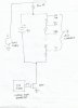
i would like to make a interface to a Data Acquisition Unit that will provide a stepping mv source to the DAU for addressing checks.

I was thinking of using a 9v battery as a voltage source (could also be an external DC power supple source) and using a bank of resistors (could also be variable resistors) to divide the voltage over 18 channels to a 37 pin cannon type connector. also there is a requirement to be able to induce a 30V peak CMV at random while the other lines are floating.

can some one advise me on how i can build this interface box...I have no idea. also is there a way to make this programmable ?

best regards
Carl
 
Something like this?
 

Attachments

  • ADtester.jpg
    ADtester.jpg
    157.4 KB · Views: 112
thank you for you sketch...yes i guess something of that type...althought when i said a 30v peak at random i ment that any one channel could be and will be subjected to that CMV. So i assume that their should be a switch of some kind to switch the CMV to a particular channel.1-18.

What value of resistors would i use to have the output for the 1-18 channels in millivolt ranges.

regards
Carl
 
thank you for you sketch...yes i guess something of that type...althought when i said a 30v peak at random i ment that any one channel could be and will be subjected to that CMV. So i assume that their should be a switch of some kind to switch the CMV to a particular channel.1-18.
Do you care that if you are reading a particular A/D input that the neighboring channels are simultaneously subjected to the common mode signal? With my proposed sketch, if you keep sampling a given channel, you should keep getting the same value regardless if the CMV is high or low. Set the 555 period so that you get like 50 A/D readings with the CMV low, and then 50 more with the CMV high. A histogram of the 100 readings would tell you if the CMV is affecting the readings.

What value of resistors would i use to have the output for the 1-18 channels in millivolt ranges.
Do you care what specific voltages are presented to the A/D inputs? If you just want them to be small, but monotonically increasing from Chan 1 to Chan 18, then just make a voltage divider consisting of say 1K resistors, with a final resistor to the positive end of the 9V battery will determine the voltage at channel 18. What is the input impedance of your A/D?
 
Last edited:
Status
Not open for further replies.

Latest threads

New Articles From Microcontroller Tips

Back
Top